Nissan Sentra B18 (2020-2025) Service Manual: Power Window Control System :: Ecu Diagnosis Information
Bcm. List of Ecu Reference. List of Ecu Reference
List of ECU Reference
|
ECU |
Reference |
|
BCM |
Values on the Diagnosis Tool |
|
Reference Value |
|
|
Fail-safe |
|
|
DTC Inspection Priority Chart |
|
|
DTC Index |
Main Power Window and Door Lock/unlock Switch. Reference Value. Reference Value
Reference Value
TERMINAL LAYOUT

PHYSICAL VALUES
|
Terminal No. (Wire color) |
Description |
Condition |
Voltage (Approx.) |
|||
|---|---|---|---|---|---|---|
|
+ |
– |
Signal name |
Input/Output |
|||
|
1 (L) |
Ground |
Rear power window motor LH DOWN signal |
Output |
Main power window and door lock/unlock switch (rear LH switch) |
Operate (DOWN) |
Battery voltage |
|
Other than above |
0 V |
|||||
|
2 (BR) |
Ground |
Rear power window motor LH UP signal |
Output |
Main power window and door lock/unlock switch (rear LH switch) |
Operate (UP) |
Battery voltage |
|
Other than above |
0 V |
|||||
|
3 (G) |
Ground |
Front power window motor LH DOWN signal |
Output |
Main power window and door lock/unlock switch (Front LH switch) |
Operate (DOWN) |
0 V |
|
Operate (AUTO) |
0 V |
|||||
|
Other than above |
Battery voltage |
|||||
|
6 (BR) |
Ground |
Rear power window motor RH DOWN signal |
Output |
Main power window and door lock/unlock switch (rear RH switch) |
Operate (DOWN) |
Battery voltage |
|
Other than above |
0 V |
|||||
|
7 (P) |
Ground |
Rear power window motor RH UP signal |
Output |
Main power window and door lock/unlock switch (rear RH switch) |
Operate (UP) |
Battery voltage |
|
Other than above |
0 V |
|||||
|
8 (BG) |
Ground |
Door lock signal |
Output |
Door lock switch in main power window and door lock/unlock switch |
Pressed |
0 V |
|
Not pressed |
Battery voltage |
|||||
|
9 (P) |
Ground |
Door unlock signal |
Output |
Door lock switch in main power window and door lock/unlock switch |
Pressed |
0 V |
|
Not pressed |
Battery voltage |
|||||
|
10 (SB) |
Ground |
Front power window motor LH UP signal |
Output |
Main power window and door lock/unlock switch (Front LH switch) |
Operate (UP) |
0 V |
|
Operate (AUTO) |
0 V |
|||||
|
Other than above |
Battery voltage |
|||||
|
11 (R) |
Ground |
Ignition ON power supply 1 |
Input |
Ignition switch ON or power window timer operates |
Battery voltage |
|
|
12 (V) |
Ground |
Ignition ON power supply 2 |
Input |
Ignition switch ON or power window timer operates |
Battery voltage |
|
|
13 (B) |
Ground |
Ground |
— |
— |
0 V |
|
|
14 (GR) |
Ground |
Front power window motor RH UP signal |
Output |
Main power window and door lock/unlock switch (Front RH switch) |
Operate (UP) |
Battery voltage |
|
Other than above |
0 V |
|||||
|
15 (LG) |
Ground |
Front power window motor RH DOWN signal |
Output |
Main power window and door lock/unlock switch (Front RH switch) |
Operate (DOWN) |
Battery voltage |
|
Other than above |
0 V |
|||||
Front Power Window Motor Lh. Reference Value
Reference Value
TERMINAL LAYOUT

Physical Values
|
Terminal No. (Wire color) |
Description |
Condition |
Voltage (Approx.) |
|||
|---|---|---|---|---|---|---|
|
+ |
– |
Signal name |
Input/Output |
|||
|
1 (G) |
Ground |
Front power window motor LH DOWN signal |
Input |
Main power window and door lock/unlock switch (Front LH switch) |
Operate (DOWN) |
0 V |
|
Operate (AUTO) |
0 V |
|||||
|
Other than above |
Battery voltage |
|||||
|
2 (SB) |
Ground |
Front power window motor LH UP signal |
Input |
Main power window and door lock/unlock switch (Front LH switch) |
Operate (UP) |
0 V |
|
Operate (AUTO) |
0 V |
|||||
|
Other than above |
Battery voltage |
|||||
|
3 (B) |
Ground |
Ground |
— |
— |
— |
|
|
4 (Y) |
Ground |
Auto ACC power supply |
Input |
Ignition switch OFF (auto ACC status) or ON |
Battery voltage |
|
|
Ignition switch OFF (not auto ACC status) |
0V |
|||||
|
6 (LG) |
Ground |
LIN communication signal |
Input/Output |
Ignition switch ON |
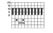 |
|
Fail Safe
Fail Safe
FAIL-SAFE CONTROL BY POWER WINDOW MOTOR
Power window motor switches power window operation to fail-safe control when malfunction is detected.
|
Detected item |
Judgment condition |
Fail-safe operation |
Recovery condition |
|---|---|---|---|
|
Non-Initialized condition |
When the motor integrated CPU detect door glass position non-initialized condition |
Auto UP operation (Anti-pinch) is forbidden |
Initialization completed |
|
Thermal protection |
When the motor integrated CPU detects thermal protection |
DOWN operation is forbidden |
After cooling, a certain amount of time has passed in the ignition switch ON state (Reference values: approximately 30 to 90 seconds, the elapsed time will be changed depending on how the temperature drops) |
|
When the motor integrated CPU detects thermal protection again when UP is operated from the above state |
Operation is forbidden (UP and DOWN is forbidden) |
||
|
Consecutive reverse operation malfunction |
When the motor integrated CPU has detected consecutively 3 times the reverse operation |
Auto UP operation (Anti-pinch) is forbidden |
Approximately 10 seconds passed or the motor integrated CPU detect door glass fully close position |
FAIL-SAFE CONTROL BY DTC
Power window motor performs fail-safe control when any DTC are detected.
| DTC | Fail-safe |
|---|---|
|
B2C41–04 |
Front power window motor LH operation is stop or inching. |
|
U1C02–08 |
Front power window motor LH operation is stop. |
Other materials:
C1f4f-82 Bcm Can Circuit 1
Dtc Description
DTC Description
DTC DETECTION LOGIC
DTC
CONSULT screen terms
(Trouble diagnosis
content)
DTC detection
conditi ...
Basic Inspection. Diagnosis and Repair Work Flow
Diagnosis and Repair Work Flow
Work Flow
Work Flow
OVERALL SEQUENCE
DETAILED FLOW
GET INFORMATION FOR SYMPTOM
Get the detailed information from the customer
about the symptom (the condition and the environment when
the incident/malfunction occurred) usi ...
Operation
Switch Name and Function
Switch Name
and Function
OPERATION AND DISPLAY OF AUTOMATIC AIR CONDITIONING
SYSTEM
Display: Display in A/C switch assembly
Air conditioning operation status is indicated
on display in A/C switch assembly.
Air conditioni ...