Nissan Sentra B18 (2020-2025) Service Manual: Power Supply, Ground & Circuit Elements :: Basic Inspection
Battery. How to Handle Battery
How to Handle Battery
CAUTION:
-
If it becomes necessary to start the engine with a booster battery and jumper cables, use a 12-volt booster battery.
-
After connecting battery cables, ensure that they are tightly clamped to battery terminals for good contact.
-
Never add distilled water through the battery gas vents.
-
Never remove the battery vent barrel.
METHODS OF PREVENTING OVER-DISCHARGE
The following precautions must be taken to prevent over-discharging a battery.
-
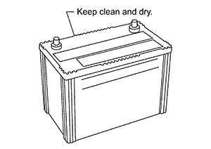
The battery surface (particularly its top) should always be kept clean and dry.
-
The terminal connections should be clean and tight.
-
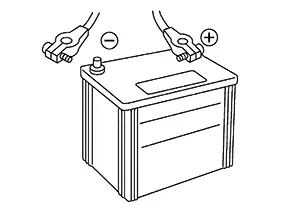
When the Nissan Sentra vehicle is not going to be used over a long period of time, disconnect the battery cable from the negative terminal. (If the Nissan Sentra vehicle has an extended storage fuse switch, turn it off.)
Work Flow
Work Flow
BATTERY DIAGNOSIS WITH 165-DSS-5000P
To diagnose and confirm the condition of the battery, use the 165-DSS-5000P.
Note:
Refer to the Instruction Manual for proper battery diagnosis procedures.
BATTERY DIAGNOSIS WITHOUT 165-DSS-5000P
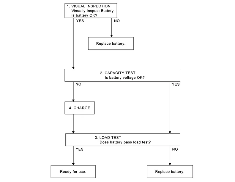
OVERALL SEQUENCE
DETAILED FLOW
-
VISUAL INSPECTION
-
-
Check battery case for cracks or bends.
-
Check battery terminals for damage.
-
Are these inspection results normal?
YES >>GO TO 2.
NO >>Replace battery. Refer to Removal and Installation (Battery).
-
-
CAPACITY TEST
-
Check battery voltage.
Is the voltage 12.35 V or more?
YES >>GO TO 3.
NO >>GO TO 4.
-
-
LOAD TEST
-
-
Check battery type and determine the specified current using the table.
Type
Current (A)
L3 EFB (CVT)
720
L2 SLI (MT)
510
-
Read load tester voltage when specified discharging current flows through battery for 15 seconds.
Note:
Follow tool manufacturers operating instructions when performing load test.
-
Is the voltage 10 V or more?
YES >>Ready for use.
NO >>Replace battery. Refer to Removal and Installation (Battery).
-
-
CHARGE
-
Charge battery following the instructions below:
-
Constant current charging may damage batteries. Therefore, charge battery by constant voltage charge mode with the maximum voltage set at 15 V.
-
Charge at least 6 hours or until the charge current becomes 4 amps or less.
-
GO TO 3.
-
Inspection and Adjustment. Additional Service When Removing Battery Negative Terminal. Additional Service When Removing Battery Negative Terminal
Special Repair Requirement
Special Repair Requirement
|
System |
Item |
Reference |
|---|---|---|
|
Engine Control System |
Idle Air Volume Learning |
Work Procedure |
|
Power Window Control System |
Power Window System Initialization |
Work Procedure |
|
Roof |
Moonroof Memory Reset/Initialization |
Description |
|
Heater & Air Conditioning Control System |
Temperature Setting Trimmer |
Temperature Setting Trimmer (Automatic Air Conditioner) |
|
Inlet Port Memory Function (FRE) |
Inlet Port Memory Function (FRE) (Automatic Air Conditioner) |
|
|
Inlet Port Memory Function (REC) |
Inlet Port Memory Function (REC) (Automatic Air Conditioner) |
|
|
Target Evaporator Temp Upper Limit |
Target Evaporator Temp Upper Limit (Automatic Air Conditioner) Target Evaporator Temp Upper Limit (Manual Air Conditioner) |
|
|
Foot Position Setting Trimmer |
Foot Position Setting Trimmer (Automatic Air Conditioner) Foot Position Setting Trimmer (Manual Air Conditioner) |
|
|
Audio, Visual & Navigation System |
Audio (Radio Preset) |
Refer to Owner's Manual. |
|
Navigation System |
Refer to Owner's Manual. |
Fuse Inspection. How to Check. How to Check
How To Check
-
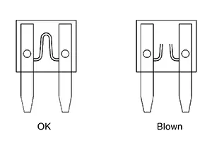
If fuse is blown, be sure to eliminate cause of malfunction before installing new fuse.
-
Use fuse of specified rating. Never use fuse of more than specified rating.
-
Do not partially install fuse; always insert it into fuse holder properly.
-
Remove fuse for “ELECTRICAL PARTS (BAT)� if Nissan Sentra vehicle is not used for a long period of time.
EXTENDED STORAGE SWITCH (IF SO EQUIPPED)
Note:
-
When extended storage switch is pulled out, a message may be shown in the meter or display. To turn message/display off, push extended storage switch in.
-
The following information is related to extended storage switch (shipping mode). For information related to BCM shipping mode, refer to System Description.
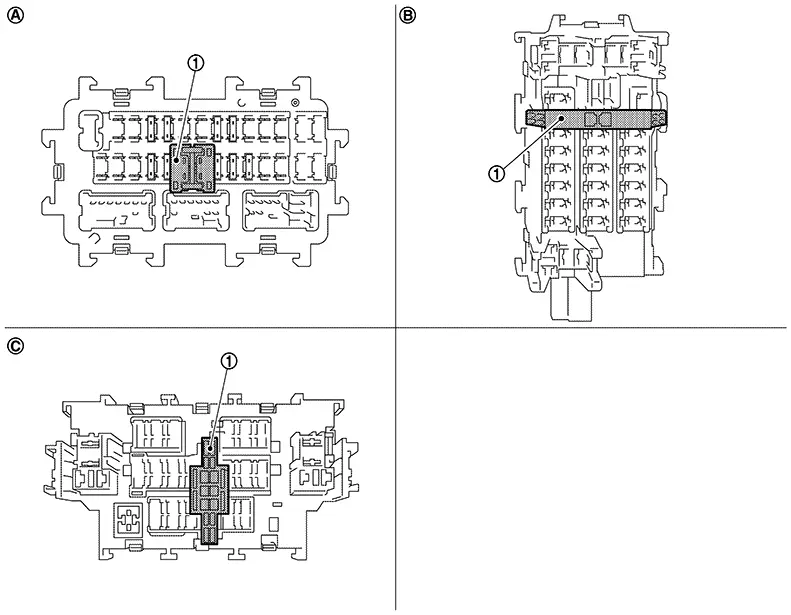
The following switch may be mounted on the fuse block (Junction Box) for transportation and storage.
|
|
Extended storage switch |
||||
|
|
Type A |
|
Type B |
|
Type C |

Remove the extended storage switch if it interferes when checking fuses.
How/When to turn Extended Storage Switch ON/OFF
CAUTION:
-
Ignition switch OFF when operating the extended storage switch.
-
Under normal conditions, keep the extended storage switch in ON state. Never operate the extended storage switch except when necessary.
-
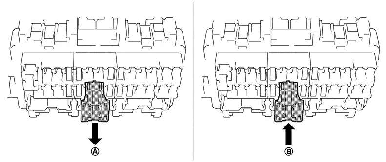
Type A
-
To place the extended storage switch in the OFF position, pull out in
 direction as shown in the figure.
 -
To place the extended storage switch in the ON position, press in
 direction as shown in the figure.
-
-
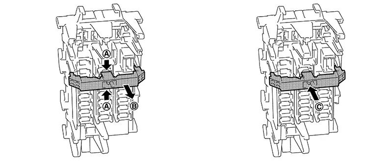
Type B
-
To place the extended storage switch in the OFF position, pinch tabs
of the switch and pull out in direction as shown in the figure. -
To place the extended storage switch in the ON position, press in
 direction as shown in the figure.
-
-
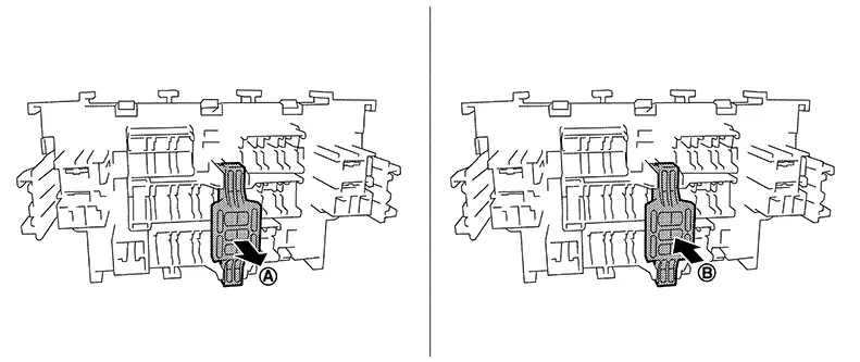
Type C
-
To place the extended storage switch in the OFF position, pull out in
direction as shown in the figure. -
To place the extended storage switch in the ON position, press in
direction as shown in the figure.
-
How To Remove Extended Storage Switch
Type A
-
Ignition switch OFF.
-
Place the extended storage switch in the OFF position.
-
Pinch tabs
and tilt to disengage the extended storage
switch. Pinch tabs to remove the extended storage switch.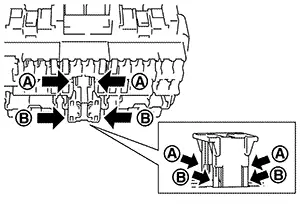
CAUTION:
For bus bar type extended storage switch, never replace bus bar with a fuse, or fuse may continually open.
Note:
-
Extended storage switch and fuse (or bus bar) are removed together. Remove fuse (or bus bar) from extended storage switch, if necessary.
-
Install removed fuse (or bus bar) to fuse block.
-
Extended storage switch is for transportation and storage. Reinstallation of switch is not required after removal, but fuse (or bus bar) must be reinstalled/pushed back in to activate all electrical systems and turn message off (which may be shown in meter/display).
-
Type B
-
Ignition switch OFF.
-
Place the extended storage switch in the OFF position.
-
Pinch tabs
and firmly pull out the extended storage
switch in direction.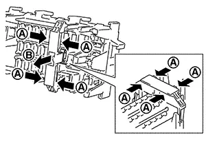
CAUTION:
For bus bar type extended storage switch, never replace bus bar with a fuse, or fuse may continually open.
Note:
-
Extended storage switch and fuse (or bus bar) may be removed together. Remove fuse (or bus bar) from extended storage switch, if necessary.
-
Install removed fuse (or bus bar) to fuse block.
-
Extended storage switch is for transportation and storage. Reinstallation of switch is not required after removal, but fuse (or bus bar) must be reinstalled/pushed back in to activate all electrical systems and turn message off (which may be shown in meter/display).
-
Type C
-
Ignition switch OFF.
-
Place the extended storage switch in the OFF position.
-
Pinch tabs
and firmly pull out the extended storage
switch in direction.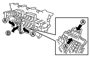
CAUTION:
For bus bar type extended storage switch, never replace bus bar with a fuse, or fuse may continually open.
Note:
-
Extended storage switch and fuse (or bus bar) are removed together. Remove fuse (or bus bar) from extended storage switch, if necessary.
-
Install removed fuse (or bus bar) to fuse block.
-
Extended storage switch is for transportation and storage. Reinstallation of switch is not required after removal, but fuse (or bus bar) must be reinstalled/pushed back in to activate all electrical systems and turn message off (which may be shown in meter/display).
-
Fusible Link Inspection. Fusible Link. Fusible Link
Fusible Link
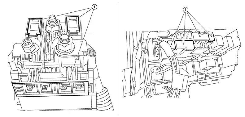
A melted fusible link can be detected either by visual inspection or by feeling with a finger tip. If its condition is questionable, use circuit tester or test lamp.
|
1 |
: Fusible link |
CAUTION:
-
If fusible link should melt, it is possible that critical circuit (power supply or large current carrying circuit) is shorted. In such a case, carefully check and eliminate cause of malfunction.
-
Never wrap outside of fusible link with vinyl tape. Important: Never let fusible link touch any other wiring harness, vinyl or rubber parts.
Other materials:
P0447 Evap Canister Vent Control Valve
Dtc Description
DTC Description
DTC DETECTION LOGIC
DTC
CONSULT screen terms
(Trouble diagnosis
content)
DTC detection
condition
...
Sonar Branch Line Circuit
Diagnosis Procedure
Diagnosis Procedure
CHECK CONNECTOR
Turn the ignition switch OFF.
Disconnect the battery cable from the
negative terminal.
Check the following terminals and
...
B0002-09 Driver Air Bag Module
Dtc Description
DTC Description
DTC DETECTION LOGIC
DTC No.
CONSULT screen terms
(Trouble diagnosis
content)
DTC detecting condition
...