Nissan Sentra B18 (2020-2025) Service Manual: Power Supply, Ground & Circuit Elements :: Removal and Installation
Battery. Exploded View
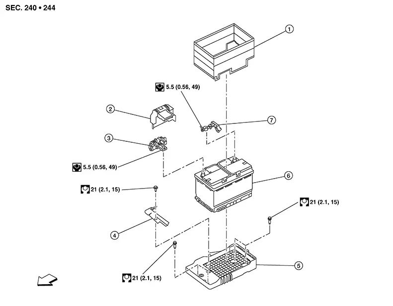
Exploded View
|
1. |
Battery cover |
2. |
Positive terminal cover |
3. |
Fusible link box (battery) |
|
4. |
Battery bracket |
5. |
Battery tray |
6. |
Battery |
|
7. |
Negative terminal |
|
Front |

Battery Disconnect
Battery Disconnect
Warning:
Battery acid and battery acid fumes are extremely dangerous and can cause severe burns and explosion. To help reduce the risk of personal injury:
-
Wear appropriate goggles and protective clothing.
-
Always properly ventilate the area where the service is being performed.
-
Do not allow battery fluid to come in contact with skin, eyes, fabrics, or painted surfaces.
-
To avoid arcing, remove the negative (-) battery cable first and attach the (-) negative battery cable last.
-
If acid contacts eyes, skin, or clothing, immediately flush with water for 15 minutes and seek medical attention.
REMOVAL
-
Loosen the battery terminal nuts and disconnect both battery negative and positive terminals.
CAUTION:
To prevent damage to the parts, disconnect the battery negative terminal first.
INSTALLATION
Installation is in the reverse order of removal.
CAUTION:
-
Replace the fusible link box (battery) if it has been dropped or sustained an impact.
-
Perform "ADDITIONAL SERVICE WHEN REMOVING BATTERY NEGATIVE TERMINAL". Refer to Special Repair Requirement.
Removal and Installation (battery)
Removal and Installation (Battery)
REMOVAL
Disconnect battery. Refer to Battery Disconnect.
CAUTION:
To prevent damage to the parts, disconnect the battery negative terminal first.
Remove battery cover from battery.
Remove bolt and battery bracket from battery tray.
Remove battery.
INSTALLATION
Installation is in the reverse order of removal.
CAUTION:
-
To prevent damage to the parts, connect the battery positive terminal first.
-
Ensure battery cables are tightly clamped to battery terminals for good contact.
-
Check battery terminal for poor connection caused by corrosion.
-
Perform "ADDITIONAL SERVICE WHEN REMOVING BATTERY NEGATIVE TERMINAL". Refer to Special Repair Requirement.
Battery Tray. Exploded View
Exploded View
|
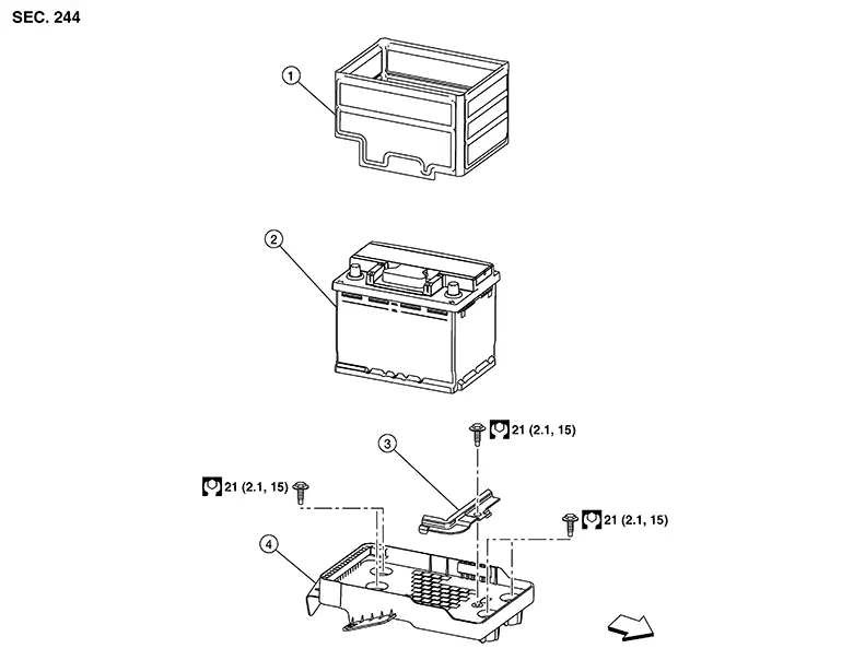
1. |
Battery cover |
2. |
Battery |
3. |
Battery bracket |
|
4. |
Battery tray |
|
Front |
Removal and Installation
Removal and Installation
Removal
Remove battery. Refer to Removal and Installation.
CAUTION:
To prevent damage to the parts, disconnect the battery negative terminal first.
Remove bolts and battery tray. Refer to Exploded View.
Installation
Installation is in the reverse order of removal.
CAUTION:
-
Perform "ADDITIONAL SERVICE WHEN REMOVING BATTERY NEGATIVE TERMINAL". Refer to Special Repair Requirement.
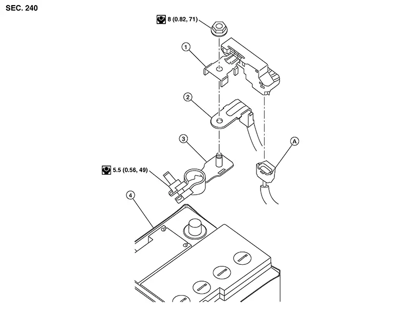
Battery Terminal with Fusible Link. Exploded View
Exploded View
|
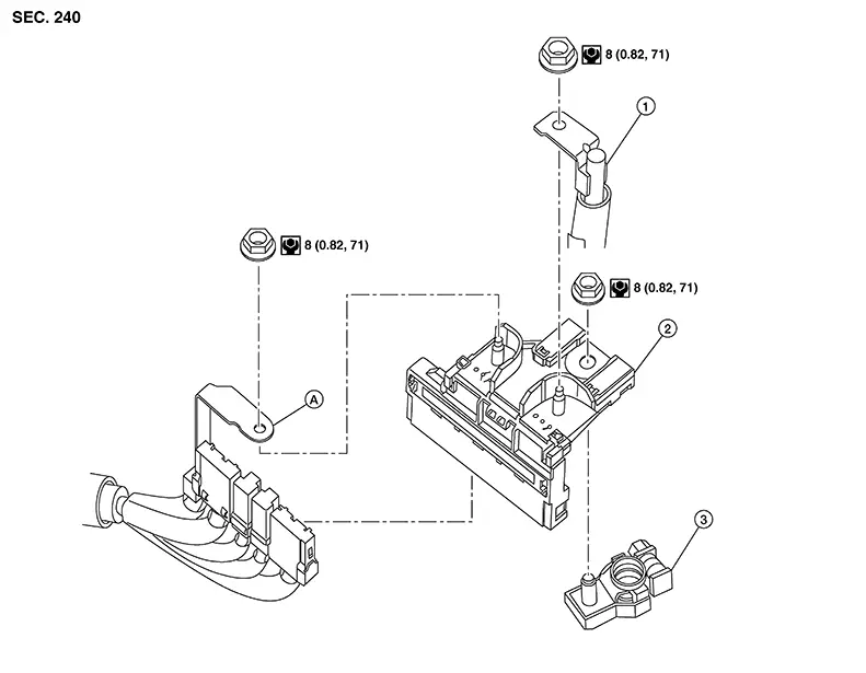
1. |
Positive battery cable |
2. |
Fusible link box (battery) |
3. |
Positive battery terminal |
|
A. |
Fusible link harness connector |
Removal and Installation
Removal and Installation
REMOVAL
Disconnect battery. Refer to Battery Disconnect.
CAUTION:
To prevent damage to the parts, disconnect the battery negative terminal first.
Remove nuts
(A), positive cables (1), and harness connector cable (B). 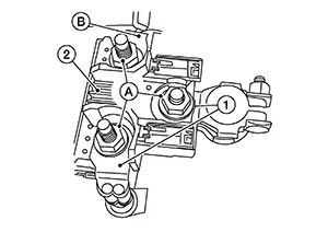
Disconnect harness connectors and remove fusible link box (battery).
INSTALLATION
Installation is in the reverse order of removal.
CAUTION:
-
To prevent damage to the parts, connect the battery positive terminal first.
-
Perform "ADDITIONAL SERVICE WHEN REMOVING BATTERY NEGATIVE TERMINAL". Refer to Special Repair Requirement.
Battery Current Sensor. Exploded View
Exploded View
|
1. |
Battery current sensor |
2. |
Negative battery cable |
3. |
Negative battery terminal |
|
4. |
Battery |
A. |
Current sensor harness connector |
Removal and Installation
Removal and Installation
REMOVAL
Disconnect battery. Refer to Battery Disconnect.
CAUTION:
To prevent damage to the parts, disconnect the battery negative terminal first.
Disconnect the harness connector from battery current sensor.
Remove the nut and battery current sensor from negative terminal.
INSTALLATION
Installation is in the reverse order of removal.
CAUTION:
Perform "ADDITIONAL SERVICE WHEN REMOVING BATTERY NEGATIVE TERMINAL". Refer to Special Repair Requirement.
Other materials:
Configuration (distance Sensor)
Work Procedure
Work Procedure
Since vehicle specifications are not included in the
distance sensor after replacement, it is required to write Nissan Sentra vehicle
specifications with CONSULT.
Configuration has three functions as follows.
...
P155b Energy Management Control
Dtc Description
DTC Description
DTC DETECTION LOGIC
DTC
CONSULT screen terms
(Trouble diagnosis
content)
DTC detection
condition
...
Windows
Power windows
WARNING
Ensure that all passengers keep their hands, arms, and other body parts
inside the Nissan Sentra while the vehicle is moving and before closing any
windows. Always use the window lock switch to prevent unintended operation of
the power windows.
To reduce the ris ...