Nissan Sentra Service Manual: Power supply and ground circuit
WITH INTELLIGENT KEY SYSTEM
WITH INTELLIGENT KEY SYSTEM : Diagnosis Procedure
Regarding Wiring Diagram information, refer to BCS-51, "Wiring Diagram".
1.Check fuses and fusible link
Check that the following fuses and fusible link are not blown.
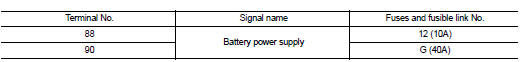
Is the fuse blown? Yes >> replace the blown fuse or fusible link after repairing the affected circuit.
No >> go to 2.
2.Check power supply circuit
- Disconnect bcm connector M85.
- Check voltage between bcm connectorM85 and ground.
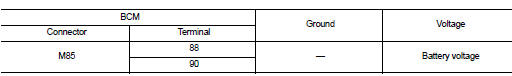
Is the inspection result normal? Yes >> go to 3.
No >> repair harness or connector.
3.Check ground circuit
Check continuity between bcm connector m85 and ground.
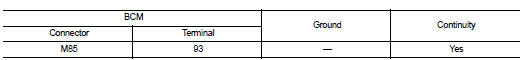
Is the inspection result normal? Yes >> inspection end.
No >> repair harness or connector.
WITHOUT INTELLIGENT KEY SYSTEM
WITHOUT INTELLIGENT KEY SYSTEM : Diagnosis Procedure
Regarding wiring diagram information, refer to bcs-111, "wiring diagram".
1.Check fuses and fusible link
Check that the following fuses and fusible link are not blown.
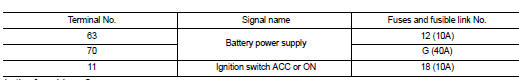
Is the fuse blown? Yes >> replace the blown fuse or fusible link after repairing the affected circuit.
No >> go to 2.
2.Check power supply circuit
- Turn ignition switch off
- Disconnect bcm connectors.
- Check voltage between bcm connector and ground.
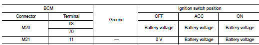
Is the inspection result normal? Yes >> go to 3.
No >> repair harness or connector.
3.Check ground circuit
Check continuity between bcm connector and ground.
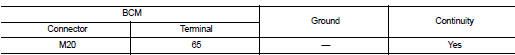
Is the inspection result normal? Yes >> inspection end.
No >> repair harness or connector.
 Low tire pressure warning lamp
Component Function Check
1.CHECK THE ILLUMINATION OF THE LOW TIRE PRESSURE WARNING LAMP
Check that the low tire pressure warning lamp is turned OFF after
illuminating for approximately 1 second,
...

Other materials:
System
Tire pressure monitoring system
TIRE PRESSURE MONITORING SYSTEM : System Diagram
TIRE PRESSURE MONITORING SYSTEM : System Description
The BCM has pressure judgment and trouble diagnosis functions. When the
BCM detects low inflation pressure
or another unusual symptom, the low tire pr ...
Diagnosis description : permanent diagnostic
trouble code (permanent DTC)
Permanent DTC is defined in SAE J1979/ISO 15031-5 Service $0A.
ECM stores a DTC issuing a command of turning on MIL as a permanent DTC and
keeps storing the DTC as
a permanent DTC until ECM judges that there is no presence of malfunction.
Permanent DTCs cannot be erased by using the erase f ...
Rear disc brake
BRAKE PAD
BRAKE PAD : Exploded View
Upper sliding pin bolt
Lower sliding pin bolt
Bushing
Cylinder body
Inner shim cover
Inner shim
Inner pad (with pad wear sensor)
Pad retainer
Torque member
Outer pad
Outer shim
Outer shim cover
Apply rubber grease
Molykote A ...
