Nissan Sentra Service Manual: System description
Component parts
Component parts location
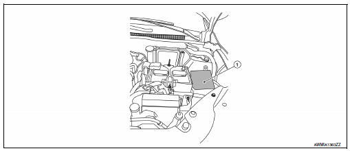
- Ipdm e/r
System
Relay control system
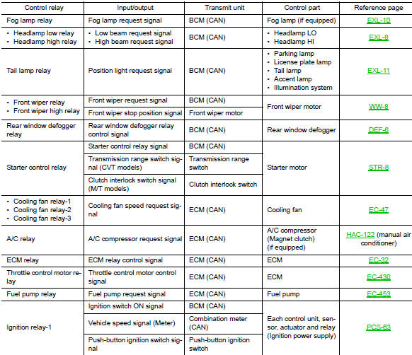
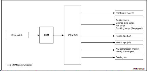
Relay control system : system diagram
System diagram
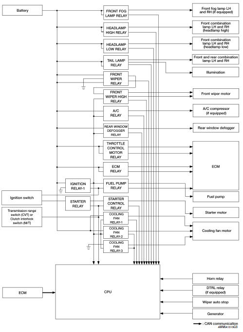
Relay control system : system description
Ipdm e/r activates the internal control circuit to perform the relay on-off control according to the input signals from various sensors and the request signals received from control units via can communication.
Caution:
To prevent damage to the parts, ipdm e/r integrated relays cannot be removed.
Power consumption control system
POWER CONSUMPTION CONTROL SYSTEM : System Diagram
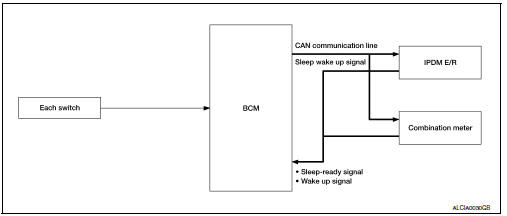
POWER CONSUMPTION CONTROL SYSTEM : System Description
Outline
- Ipdm e/r incorporates a power consumption control function that reduces the power consumption according to the vehicle status.
- IPDM E/R changes its status (control mode) with the sleep wake up signal received from BCM via CAN communication.
Normal mode (wake-up)
- Can communication is normally performed with other control units.
- Individual unit control by ipdm e/r is normally performed.
Low power consumption mode (sleep)
- Low power consumption control is active.
- Can transmission is stopped.
Sleep mode activation
- Ipdm e/r judges that the sleep-ready conditions are fulfilled when the ignition switch is off and none of the conditions below are present. Then it transmits a sleep-ready signal (ready) to bcm via can communication.
- Outputting signals to actuators
- Switches or relays operating
- Output requests are being received from control units via can communication.
- Ipdm e/r stops can communication and enters the low power consumption mode when it receives a sleep wake up signal (sleep) from bcm and the sleep-ready conditions are fulfilled.
Wake-up operation
- Ipdm e/r changes from the low power consumption mode to the normal mode when it receives a sleep wake-up signal (wake up) from bcm or any of the following conditions is fulfilled. In addition, it transmits a sleep-ready signal (not-ready) to bcm via can communication to report the can communication start.
- Ignition switch on
- An output request is received from a control unit via can communication.
Diagnosis system (ipdm e/r)
Diagnosis Description
Auto active test
Description
In auto active test, the ipdm e/r sends a drive signal to the following systems to check their operation.
- Front wiper (LO, HI)
- Parking lamp
- License plate lamp
- Tail lamp
- Front fog lamp (if equipped)
- Headlamp (lo, hi)
- A/c compressor (magnet clutch) (if equipped)
- Cooling fan
Operation procedure
Note:
Never perform auto active test in the following conditions.
- Passenger door is open
- Consult is connected
- Close the hood and lift the wiper arms from the windshield. (Prevent windshield damage due to wiper operation)
Note:
When auto active test is performed with hood opened, sprinkle water on windshield beforehand.
- Turn the ignition switch off.
- Turn the ignition switch on, and within 20 seconds, press the driver door switch 10 times. Then turn the ignition switch off.
- Turn the ignition switch on within 10 seconds. After that the horn sounds once and the auto active test starts.
- After a series of the following operations is repeated 3 times, auto active test is completed.
Note:
- When auto active test has to be cancelled halfway through test, turn the ignition switch off.
- When auto active test is not activated, door switch may be the cause. Check door switch. Refer to dlk-255, "component inspection".
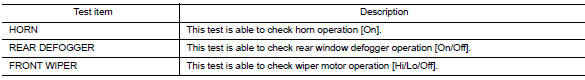
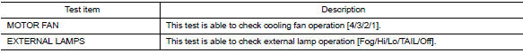
Inspection in auto active test
When auto active test is actuated, the following operation sequence is repeated 3 times.
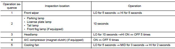
Concept of auto active test
- Ipdm e/r starts the auto active test with the door switch signals
transmitted by bcm via can communication.
Therefore, the can communication line between ipdm e/r and bcm is considered normal if the auto active test starts successfully.
- The auto active test facilitates troubleshooting if any systems controlled by ipdm e/r cannot be operated.
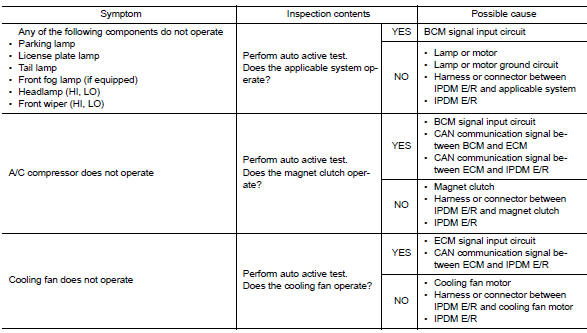
Diagnosis chart in auto active test
CONSULT Function (IPDM E/R)
Application item
Consult performs the following functions via can communication with ipdm e/r.
| Direct diagnostic mode | Description |
| Ecu identification | The ipdm e/r part number is displayed |
| Self Diagnostic Result | The ipdm e/r self diagnostic results are displayed. |
| Data Monitor | The IPDM E/R input/output data is displayed in real time. |
| Active test | The ipdm e/r activates outputs to test components. |
| CAN Diag Support Mntr | The result of transmit/receive diagnosis of CAN communication is displayed. |
Ecu identification
The IPDM E/R part number is displayed.
Self diagnostic result
Refer to PCS-48, "DTC Index".
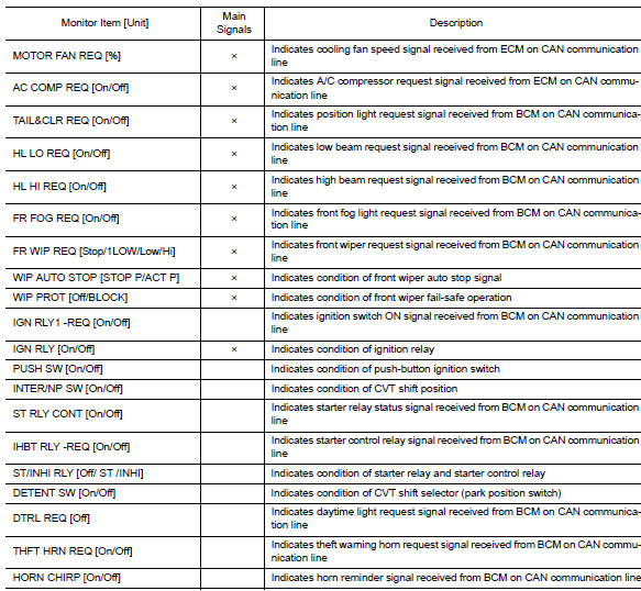
Data monitor
Active test
Can diag support mntr
Refer to lan-13, "can diagnostic support monitor".
 Precaution
Precaution for supplemental restraint system (srs) "air bag" and "seat
belt pre-tensioner"
The supplemental restraint system such as “air bag” and “seat belt pre- ...
 Ecu diagnosis information
Ipdm e/r (intelligent power distribution module engine room)
Reference Value
Values on the diagnosis tool
Terminal layout
Physical values
Fail-Safe
Can communic ...
Other materials:
C1607, C1608 EPS Control unit
DTC Logic
DTC DETECTION LOGIC
Dtc
Display item
Malfunction detected condition
Possible cause
C1607
EEPROM
When the memory (EEPROM) system malfunction is
detected in EPS control unit.
Eps control unit
C1608
CONTROL UNIT
When the internal malfuncti ...
Information voice commands
The following voice commands are available for
the information functions of the Navigation System:
Traffic
Fuel Prices
Stocks
Movie Listings
Current Weather
Weather Map
5 — day Forecast
6 — hour Forecast
For more information about these commands,
see the separate Navigatio ...
Abbreviations
Abbreviation List
The following ABBREVIATIONS are used:
A
ABBREVIATION
DESCRIPTION
A/C
Air conditioner
A/C
Air conditioning
A/F sensor
Air fuel ratio sensor
A/T
Automatic transaxle/transmission
ABS
Anti-lock braking sys ...
