Nissan Sentra Service Manual: P2004 Intake manifold runner control valve
DTC Logic
DTC DETECTION LOGIC
| DTC No. | CONSULT screen terms (Trouble diagnosis content) | DTC detecting condition | Possible cause |
| P2004 | TUMBLE CONT/V (Intake manifold runner control stuck open bank 1) | The target angle of intake manifold runner control valve controlled by ECM and the input signal from intake manifold runner control valve position sensor is not in the normal range. |
|
DTC CONFIRMATION PROCEDURE
1.PRECONDITIONING
If DTC Confirmation Procedure has been previously conducted, always turn ignition switch OFF and wait at least 10 seconds before conducting the next test.
TESTING CONDITION:
- Before performing the following procedure, confirm that battery voltage is more than 11 V at idle.
- Always perform the test at a temperature above −7В°C (19В°F)
>> GO TO 2.
2.PERFORM DTC CONFIRMATION PROCEDURE
 With CONSULT
- Turn ignition switch ON.
- Select “DATA MONITOR” mode with CONSULT.
- Make sure that “COOLANT TEMP/S” indicates between −7В°C (19В°F) to 60В°C
(140В°F).
If not, cool engine down or warm engine up until “COOLANT TEMP/S” indicates between −7В°C (19В°F) to 60В°C (140В°F). Then go to the following steps.
- Fully release accelerator pedal and wait at least 10 seconds.
- Depress accelerator pedal and wait at least 10 seconds.
- Check 1st trip DTC.
 With GST
Following the procedure “With CONSULT” above.
Is 1st trip DTC detected? YES >> Proceed to EC-413, "Diagnosis Procedure".
NO >> INSPECTION END
Diagnosis Procedure
1.CHECK INTAKE MANIFOLD RUNNER CONTROL VALVE MOTOR POWER SUPPLY
- Turn ignition switch ON
- Check the voltage between ECM harness connector.
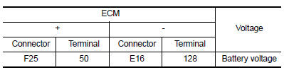
Is the inspection result normal? YES >> GO TO 3.
NO >> GO TO 2.
2.CHECK INTAKE MANIFOLD RUNNER CONTROL VALVE MOTOR POWER SUPPLY CIRCUIT
- Turn ignition switch OFF.
- Disconnect ECM harness connector.
- Disconnect IPDM E/R harness connector.
- Check the continuity between ECM harness connector and IPDM E/R harness connector.
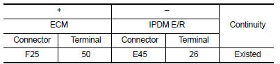
- Also check harness for short to ground.
Is the inspection result normal? YES >> Perform the trouble diagnosis for power supply circuit.
NO >> Repair or replace error-detected parts.
3.CHECK INTAKE MANIFOLD RUNNER CONTROL VALVE MOTOR OUTPUT SIGNAL CIRCUIT
- Disconnect intake manifold runner control valve motor harness connector.
- Check the continuity between intake manifold runner control valve motor harness connector and ECM harness connector.
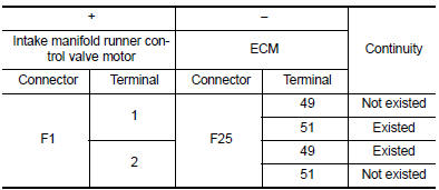
- Also check harness for short to ground and to power.
Is the inspection result normal? YES >> GO TO 4.
NO >> Repair or replace error-detected parts.
4.CHECK INTAKE MANIFOLD RUNNER CONTROL VALVE MOTOR
Check the intake manifold runner control valve motor. Refer to EC-414, "Component Inspection".
Is the inspection result normal? YES >> Check intermittent incident. Refer to GI-39, "Intermittent Incident".
NO >> Replace intake manifold assembly. Refer to EM-27, "Removal and Installation".
Component Inspection
1.CHECK INTAKE MANIFOLD RUNNER CONTROL VALVE
 With CONSULT
- Turn ignition switch ON.
- Select “DATA MONITOR” mode with CONSULT.
- Make sure that “COOLANT TEMP/S” indicates between −7В°C (19В°F) to 60В°C
(140В°F).
If not, cool engine down or warm engine up until “COOLANT TEMP/S” indicates between −7В°C (19В°F) to 60В°C (140В°F). Then go to the following steps.
- Fully release accelerator pedal and make sure that “TUMBLE POS SEN” indicates between 2.8 V to 4.1 V.
- Depress accelerator pedal and make sure that “TUMBLE POS SEN” indicates between 0.2 V to 1.4 V.
- Check 1st trip DTC.
 With GST
Following the procedure “With CONSULT” above.
Is 1st trip DTC detected? YES >> Replace intake manifold assembly. Refer to EM-27, "Removal and Installation".
NO >> GO TO 2.
2.CHECK INTAKE MANIFOLD RUNNER CONTROL VALVE MOTOR
- Turn ignition switch OFF.
- Disconnect intake manifold runner control valve motor harness connector.
- Check the resistance between intake manifold runner control valve motor terminals as per the following.
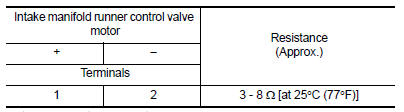
Is the inspection result normal? YES >> INSPECTION END
NO >> Replace intake manifold assembly. Refer to EM-27, "Removal and Installation".
 P1805 Brake switch
DTC Logic
DTC DETECTION LOGIC
DTC No.
CONSULT screen terms
(Trouble diagnosis content)
DTC detecting condition
Possible cause
P1805
BRAKE SW/CIRCUIT
(Brake switch c ...
 P2014, P2016, P2017, P2018 Intake manifold runner control valve position
sensor
P2014, P2016, P2017, P2018 Intake manifold runner control valve position
sensor
DTC Logic
DTC DETECTION LOGIC
NOTE:
If DTC P2014, P2016, P2017 or P2018 is displayed with DTC P0643, first
perform the trouble diagnosis
for DTC P0643. Refer to EC-353, "DTC Logic".
...
Other materials:
Headlamp (lo) circuit
Description
The ipdm e/r (intelligent power distribution module engine room) controls the
headlamp low relay based on
inputs from the bcm over the can communication lines. When the headlamp low
relay is energized, power
flows through fuses 43 and 44, located in the ipdm e/r. Power then flows ...
Battery
Keep the battery surface clean and dry.
Clean the battery with a solution of baking
soda and water.
Make certain the terminal connections are
clean and securely tightened.
If the vehicle is not to be used for 30 days or
longer, disconnect the negative (-) battery
terminal cable to p ...
C1143 Steering angle sensor
DTC Logic
DTC DETECTION LOGIC
DTC
Display Item
Malfunction detected condition
Possible causes
C1143
ST ANG SEN CIRCUIT
When a malfunction is detected in steering angle sensor.
Harness or connector
Steering angle sensor
ABS actuator and electric u ...
