Nissan Sentra Service Manual: C1143 Steering angle sensor
DTC Logic
DTC DETECTION LOGIC
| DTC | Display Item | Malfunction detected condition | Possible causes |
| C1143 | ST ANG SEN CIRCUIT | When a malfunction is detected in steering angle sensor. |
|
DTC CONFIRMATION PROCEDURE
1.CHECK SELF DIAGNOSTIC RESULT
 With CONSULT
-
Turn ignition switch ON.
-
Perform self diagnostic result.
Is DTC C1143 detected? YES >> Proceed to diagnosis procedure. Refer to BRC-80, "Diagnosis Procedure".
NO >> Inspection End.
Diagnosis Procedure
Regarding Wiring Diagram information, refer to BRC-44, "Wiring Diagram".
1.CONNECTOR INSPECTION
-
Turn ignition switch OFF.
-
Disconnect ABS actuator and electric unit (control unit) and steering angle sensor connectors.
-
Check connectors and terminals for deformation, disconnection, looseness or damage.
Is the inspection result normal? YES >> GO TO 2.
NO >> Repair or replace as necessary.
2.CHECK STEERING ANGLE SENSOR MOUNTING CONDITION
Check steering angle sensor mounting condition.
Is the inspection result normal? YES >> GO TO 3.
NO >> Repair or replace malfunctioning components.
3.Check steering angle sensor power supply
-
Turn ignition switch OFF.
-
Disconnect steering angle sensor connector.
-
Turn ignition switch ON.
-
Check voltage between steering angle sensor connector M14 terminal 4 and ground.
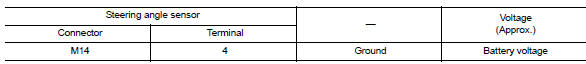
Is the inspection result normal? Yes >> go to 4.
No >> check the following:
-
Repair or replace harness.
-
Fuse
4.Check steering angle sensor ground circuit
-
Turn ignition switch off.
-
Check continuity between steering angle sensor connector m14 terminal 1 and ground.
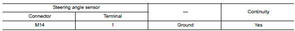
Is the inspection result normal? Yes >> go to 5.
No >> repair or replace malfunctioning components.
5.Check can communication line
Check “strg branch line circuit”. Refer to lan-66, "diagnosis procedure" (type 1) or lan-79, "diagnosis procedure" (type 2).
Is the inspection result normal? Yes >> replace abs actuator and electric unit (control unit). Refer to brc-110, "removal and installation".
No >> repair or replace malfunctioning components.
 C1142 Press sensor
DTC Logic
DTC DETECTION LOGIC
DTC
Display Item
Malfunction detected condition
Possible causes
C1142
PRESS SEN CIRCUIT
When a malfunction is detected in master cylinde ...
 1144 Incomplete steering angle sensor adjustment
DTC Logic
Dtc detection logic
Dtc
Display item
Malfunction detected condition
Possible causes
C1144
St ang sen signal
When neutral position adjustment of steering angl ...
Other materials:
Work Flow
STEP
DESCRIPTION
STEP 1
Get detailed information about the conditions and the
environment when the incident occurred.
The following are key pieces of information required to make a good
analysis:
WHAT
Vehicle Model, Engine, Transmission/Transaxle and ...
P0222, P0223 TP Sensor
DTC Logic
DTC DETECTION LOGIC
NOTE:
If DTC P0222 or P0223 is displayed with DTC P0643, first perform the
trouble diagnosis for DTC P0643.
Refer to EC-353, "DTC Logic".
DTC No.
CONSULT screen terms
(Trouble diagnosis content)
DTC detecting condition
Possible caus ...
Using the system
Initialization
When the ignition switch is in the ON position,
NISSAN Voice Recognition is initialized, which
takes a few seconds. When completed, the system
is ready to accept voice commands. If
the button is pressed before the
initialization
completes, the system will announce: “Voice
...
