Nissan Sentra Service Manual: Moonroof switch
Description
Transmits switch operation signal to moonroof motor assembly.
Diagnosis Procedure
Regarding Wiring Diagram information, refer to RF-13, "Wiring Diagram".
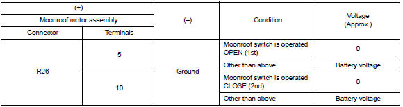
1.Check moonroof switch input signal
- Turn ignition switch on.
- Check voltage between moonroof motor assembly harness connector R26 and ground.
Is the inspection result normal? Yes >> inspection end.
No >> go to 2.
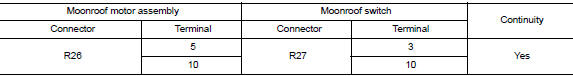
2.Check moonroof switch circuit
- Turn ignition switch OFF.
- Disconnect moonroof motor assembly connector and moonroof switch connector.
- Check continuity between moonroof motor assembly harness connector R26 and moonroof switch harness connector R27.
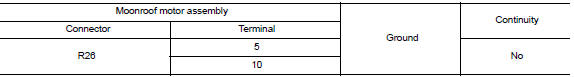
- Check continuity between moonroof motor assembly harness connector R26 and ground.
Is the inspection result normal? YES >> GO TO 3.
NO >> Repair or replace the harness or connectors.
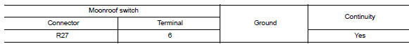
3.Check moonroof switch ground circuit
Check continuity between moonroof switch harness connector r27 and ground.
Is the inspection result normal? YES >> GO TO 4.
NO >> Repair or replace the harness or connectors.
4.Check moonroof switch
Check moonroof switch.
Refer to rf-25, "component inspection".
Is the inspection result normal? Yes >> go to 5.
No >> replace moonroof switch. Refer to rf-50, "removal and installation".
5.Check intermittent incident
Refer to gi-39, "intermittent incident".
>> Inspection end.
Component inspection
Moonroof switch
1. Check moonroof switch
- Turn ignition switch off.
- Disconnect moonroof switch.
- Check continuity between moonroof switch terminals.
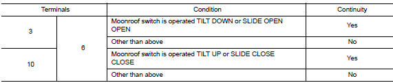
Is the inspection result normal? Yes >> moonroof switch is ok.
No >> replace moonroof switch. Refer to rf-50, "removal and installation".
 Power supply and ground circuit
Body control system
Body control system : diagnosis procedure
Regarding wiring diagram information, refer to bcs-51, "wiring diagram".
1.Check fuses and fusible link
Check that the follo ...
 Door switch
Component Function Check
1.Check function
Select DOOR LOCK of BCM using CONSULT
Select door sw-dr, door sw-as in data monitor mode
Check that the function operates normally according to the f ...
Other materials:
Battery
Keep the battery surface clean and dry.
Clean the battery with a solution of baking
soda and water.
Make certain the terminal connections are
clean and securely tightened.
If the vehicle is not to be used for 30 days or
longer, disconnect the negative (-) battery
terminal cable to p ...
Inspection and adjustment
Additional service when replacing control unit
Additional service when replacing control unit : description
Memory reset procedure
Please observe the following instructions at confirming the moonroof
operation.
Note:
Do not disconnect the electronic power while the moonroof is operating ...
P0507 ISC System
Description
The ECM controls the engine idle speed to a specified level through the fine
adjustment of the air, which is let
into the intake manifold, by operating the electric throttle control actuator.
The operating of the throttle valve is
varied to allow for optimum control of the engine ...
