Nissan Sentra Service Manual: Power supply and ground circuit
Body control system
Body control system : diagnosis procedure
Regarding wiring diagram information, refer to bcs-51, "wiring diagram".
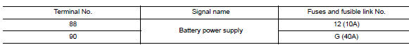
1.Check fuses and fusible link
Check that the following fuses and fusible link are not blown.
Is the fuse blown? Yes >> replace the blown fuse or fusible link after repairing the affected circuit.
No >> go to 2.
2.Check power supply circuit
- Disconnect BCM connector M85.
- Check voltage between bcm connector m85 and ground.
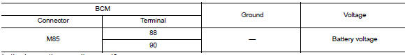
Is the inspection result normal? Yes >> go to 3.
No >> repair harness or connector.
3.Check ground circuit
Check continuity between BCM connector M85 and ground.
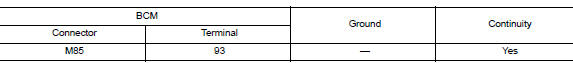
Is the inspection result normal? Yes >> inspection end.
No >> repair harness or connector.
Moonroof motor assembly
Moonroof motor assembly : description
- Bcm supplies power.
- Cpu is integrated in moonroof motor assembly.
- Tilts up/down & slides open/close by moonroof switch operation.
- In order to close moonroof lid certainly with the signal from combination meter at the time of high speed run, the moonroof motor torque at the time of tilt-down operation is controlled.
Moonroof motor assembly : component function check
1. Check moonroof motor function
Check whether tilt up/down & slide open/close functions operate with moonroof switch normally? Is the inspection result normal? YES >> Moonroof motor assembly is OK.
NO >> Refer to RF-20, "MOONROOF MOTOR ASSEMBLY : Diagnosis Procedure".
Moonroof motor assembly : diagnosis procedure
Regarding wiring diagram information, refer to rf-13, "wiring diagram".
Moonroof motor assembly
1. Check power supply circuit
- Turn ignition switch off.
- Disconnect moonroof motor assembly connector.
- Turn ignition switch on.
- Check voltage between moonroof motor assembly connector r26 and ground.
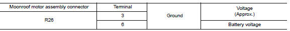
Is the inspection result normal? YES >> GO TO 2.
NO >> GO TO 3.
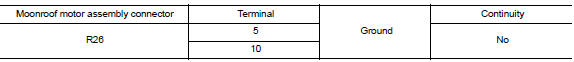
2. Check ground circuit
- Turn ignition switch off.
- Check continuity between moonroof motor assembly connector R26 and ground.

Is the inspection result normal? YES >> GO TO 5.
NO >> Repair or replace the harness or connectors.
3. Check moonroof motor circuit
- Turn ignition switch off.
- Disconnect bcm.
- Check continuity between bcm connector m85 and moonroof motor assembly connector r26.
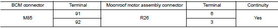
- Check continuity between BCM connector M85 and ground.
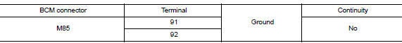
Is the inspection result normal? Yes >> go to 4.
NO >> Repair or replace the harness or connectors.
4. Check bcm power supply
- Connect bcm.
- Check voltage between BCM connector M85 and ground.
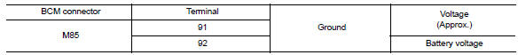
Is the inspection result normal? Yes >> check condition of harness and connectors.
No >> replace bcm. Refer to bcs-73, "removal and installation".
5. Check moonroof switch input signal
- Connect moonroof motor assembly.
- Turn ignition switch on.
- Check voltage between moonroof motor assembly connector R26 and ground.
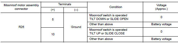
Is the inspection result normal? Yes >> go to 8.
No >> go to 6.
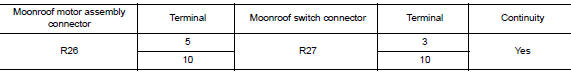
6. Check moonroof switch circuit
- Turn ignition switch off.
- Disconnect moonroof motor assembly and moonroof switch.
- Check continuity between moonroof motor assembly connector r26 and moonroof switch connector r27.
- Check continuity between moonroof motor assembly connector r26 and ground.
Is the inspection result normal? YES >> GO TO 7.
NO >> Repair or replace the harness and connectors.
7. Check moonroof switch ground circuit
- Connect moonroof motor assembly.
- Check continuity between moonroof switch connector r27 and ground.

Is the inspection result normal? Yes >> refer to rf-22, "moonroof motor assembly : component inspection".
No >> repair or replace the harness or connectors.
8. Check combination meter signal
- Check signal between moonroof motor assembly connector R26 and ground with oscilloscope.
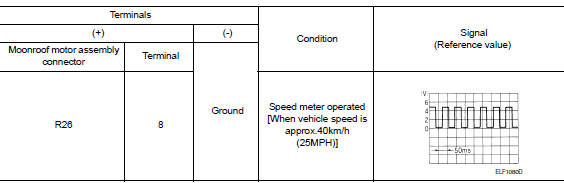
Is the inspection result normal? Yes >> replace moonroof motor assembly. Refer to rf-41, "removal and installation". After that, refer to rf-18, "additional service when replacing control unit : special repair requirement".
No >> go to 9.
9.Check combination meter circuit
- Turn ignition switch OFF.
- Disconnect combination meter.
- Check continuity between combination meter connector m24 and moonroof motor assembly connector r26.

- Check continuity between combination meter connector M24 and ground.

Is the inspection result normal? Yes >> replace combination meter. Refer to mwi-77, "removal and installation".
No >> repair or replace the harness or connectors.
Moonroof motor assembly : component inspection
Moonroof switch
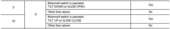
1. Check moonroof switch
- Turn ignition switch off.
- Disconnect moonroof switch.
- Check continuity between moonroof switch terminals.

Is the inspection result normal? Yes >> moonroof switch is ok.
No >> replace moonroof switch (map lamp assembly). Refer to rf-50, "removal and installation".
Moonroof motor assembly : special repair requirement
1. Perform initialization procedure
Perform initialization procedure.
Refer to rf-18, "additional service when replacing control unit : special repair requirement".
>> Go to 2.
2. Check anti-pinch operation
Check anti-pinch operation.
Refer to rf-18, "additional service when replacing control unit : special repair requirement".
Is the inspection result normal? Yes >> inspection end.
No >> check fitting adjustment. Refer to rf-40, "adjustment".

 Moonroof switch
Description
Transmits switch operation signal to moonroof motor assembly.
Diagnosis Procedure
Regarding Wiring Diagram information, refer to RF-13, "Wiring Diagram".
1.Check moonroof sw ...
Other materials:
System
Tire pressure monitoring system
TIRE PRESSURE MONITORING SYSTEM : System Diagram
TIRE PRESSURE MONITORING SYSTEM : System Description
The BCM has pressure judgment and trouble diagnosis functions. When the
BCM detects low inflation pressure
or another unusual symptom, the low tire pr ...
Steering column
Exploded View
Steering column assembly
Slide plates
lower shaft assembly
Removal and Installation
REMOVAL
CAUTION:
While removing the steering column assembly, do not
unlock the tilt lever.
Do not impact on the axis when removing steering
column assembly.
...
Compression pressure
Inspection
Warm up the engine to full operating temperature.
Release fuel pressure. Refer to EC-143, "Work Procedure".
Remove ignition coil and spark plug from each cylinder. Refer to EM-46,
"Exploded View".
Connect engine tachometer (not required in use of CONSULT). ...
