Nissan Sentra Service Manual: Transmitter
Exploded View
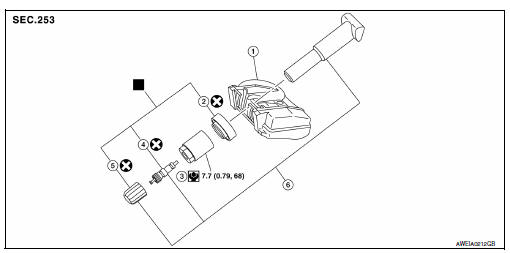
- Transmitter (tire pressure sensor)
- O-ring
- Valve stem nut
- Valve core
- Valve cap
- Valve stem assembly
 Parts that are replaced as a set
when the tire is replaced.
Removal and Installation
REMOVAL
- Remove road wheel and tire assembly using power tool.
- Remove valve cap and valve core to deflate the tire.
NOTE:
If the tire is to be reused, apply a matching mark on the tire in line with the position of the road wheel valve stem assembly for the purpose of road wheel and tire balance adjustment after installation.
- Remove the valve stem nut and allow transmitter to fall into tire.
- Lubricate the tire outside bead well with a suitable non-silicone lubricant, and remove outside of tire from the road wheel. Reach inside the tire and remove the transmitter.
CAUTION:
- Do not use silicone lubricant. Use of silicone lubricant will deteriorate the tire and road wheel.
- Be sure not to damage the road wheel or transmitter.
- Do not allow lubricant to make contact with transmitter.
- Lubricate the tire inside bead well with a suitable non-silicone lubricant, and remove inside of tire from the road wheel.
CAUTION:
- Do not use silicone lubricant. Use of silicone lubricant will deteriorate the tire and road wheel.
- Be sure not to damage the road wheel.
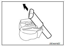
- Remove the valve stem from the transmitter as shown.
INSTALLATION
- Apply a suitable non-silicone lubricant to the tire inside bead.
CAUTION:
Do not use silicone lubricant. Use of silicone lubricant will deteriorate the tire and road wheel.
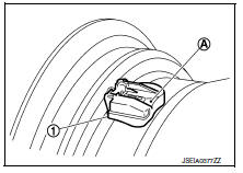
- Install the tire inside bead (1) onto the road wheel (2) in the position shown.
INSTALLATION
- Apply a suitable non-silicone lubricant to the tire inside bead.
CAUTION:
Do not use silicone lubricant. Use of silicone lubricant will deteriorate the tire and road wheel.
- Install the tire inside bead (1) onto the road wheel (2) in the position shown.
- Install the valve stem to the transmitter
- Install the O-ring to the transmitter.
CAUTION:
- Do not reuse O-ring
- Insert O-ring to the base of the transmitter.
- The base of the valve stem (A) must be positioned in the groove of the metal plate as shown.
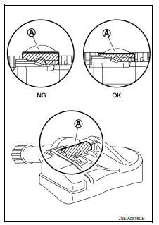
- Install transmitter (1) to road wheel while pressing at position (A).
CAUTION:
- Check that O-ring contacts horizontally with road wheel.
- Check that the base of the valve stem is positioned in the groove of the metal plate.
- Install and tighten the valve stem nut to the specified torque.
Valve stem nut tightening torque Refer to WT-50, "Exploded View".
CAUTION:
Do not use power tool for installation.
- Place road wheel on turntable of tire machine. Ensure that transmitter is 270 degrees from mounting/dismounting head.
NOTE:
Do not touch transmitter with mounting head.
- Apply a suitable non-silicone lubricant to the tire outside bead.
CAUTION:
- Do not use silicone lubricant. Use of silicone lubricant will deteriorate the tire and road wheel.
- Do not allow lubricant to make contact with transmitter.
- Install the tire outside bead onto the road wheel as normal.
NOTE:
If the tire is being reused, align the matching mark applied on the tire with the position of the road wheel valve stem assembly for the purpose of road wheel and tire balance adjustment after installation. Ensure that the tire does not rotate relative to road wheel.
- Install the valve core and inflate tire.
CAUTION:
Do not reuse valve core.
- Install the valve cap.
CAUTION:
Do not reuse valve cap.
- Balance the road wheel and tire assembly. Refer to WT-47, "Adjustment".
- Install road wheel and tire assembly in appropriate wheel position on vehicle. Refer to WT-47, "Removal and Installation".
NOTE:
If replacing the transmitter, then transmitter wake up operation must be performed. Refer to WT-22, "Work Procedure".
- Adjust neutral position of steering angle sensor. Refer to BRC-54, "Work Procedure".
Tire pressure receiver
Removal and Installation
The tire pressure receiver is integral to the remote keyless entry receiver. Refer to DLK-199, "Removal and Installation".
 Road wheel tire assembly
Exploded View
Removal and Installation
REMOVAL
Remove wheel nuts.
Remove wheel and tire.
INSTALLATION
Installation is in the reverse order of removal.
Adjustment
BALANCING WHEELS (A ...
 Service data and specifications (SDS)
Road Wheel
Tire Air Pressure
M/T - CVT MODELS
CVT MODELS
...
Other materials:
P0603 ECM
DTC Logic
DTC DETECTION LOGIC
DTC No.
CONSULT screen terms
(Trouble diagnosis content)
DTC detecting condition
Possible cause
P0603
ECM BACK UP CIRCUIT
[Internal control module keep
alive memory (KAM) error]
Malfunction in the internal back up RAM o ...
Precaution for Supplemental Restraint System (SRS) "AIR BAG" and "SEAT BELT
PRE-TENSIONER"
The Supplemental Restraint System such as “AIR BAG” and “SEAT BELT PRE-TENSIONER”,
used along
with a front seat belt, helps to reduce the risk or severity of injury to the
driver and front passenger for certain
types of collision. Information necessary to service the system ...
Fuel pressure
Work Procedure
FUEL PRESSURE RELEASE
1.FUEL PRESSURE RELEASE
With CONSULT
Turn ignition switch ON.
Perform “FUEL PRESSURE RELEASE” in “WORK SUPPORT” mode of “ENGINE” using
CONSULT
Start engine.
After engine stalls, crank it two or three times to release ...
