Nissan Sentra Service Manual: P1805 Brake switch
DTC Logic
DTC DETECTION LOGIC
| DTC No. | CONSULT screen terms (Trouble diagnosis content) | DTC detecting condition | Possible cause |
| P1805 | BRAKE SW/CIRCUIT (Brake switch circuit) | Stop lamp signal is not sent to ECM for extremely long time while the vehicle is driving. |
|
DTC CONFIRMATION PROCEDURE
1.PERFORM DTC CONFIRMATION PROCEDURE
NOTE:
Since this DTC is difficult to be confirmed, check component function to judge the normality.
>> Proceed to EC-410, "Component Function Check".
Component Function Check
1.CHECK BRAKE SWITCH FUNCTION
 With CONSULT
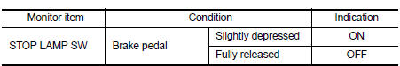
- On the CONSULT screen, select “ENGINE” >> “DATA MONITOR” >> “BRAKE SW 2”.
- Check “STOP LAMP SW” indication under the following conditions.
 Without CONSULT
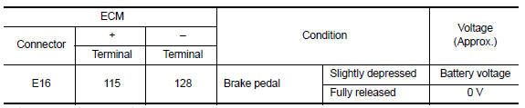
- Turn ignition switch ON.
- Check the voltage between ECM harness connector terminals under the following conditions.
Is the inspection result normal? YES >> INSPECTION END
NO >> Proceed to EC-410, "Diagnosis Procedure".
Diagnosis Procedure
1.CHECK STOP LAMP SWITCH OPERATION
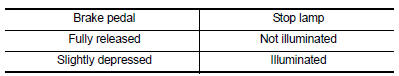
- Turn power switch OFF.
- Check the stop lamp when depressing and releasing the brake pedal.
Is the inspection result normal? YES >> GO TO 5.
NO >> GO TO 2.
2.CHECK STOP LAMP SWITCH POWER SUPPLY
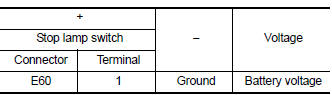
- Disconnect stop lamp switch harness connector.
- Check the voltage between stop lamp switch harness connector and ground.
- Also check harness for short to ground.
Is the inspection result normal? YES >> GO TO 4.
NO >> GO TO 3.
3.CHECK STOP LAMP SWITCH POWER SUPPLY CIRCUIT
- Pull out #30 fuse.
- Check that the fuse is not fusing.
- Check the continuity between stop lamp switch harness connector and fuse terminal.
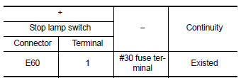
- Also check harness for short to ground and short to power.
Is the inspection result normal? YES >> Check power supply circuit for 12V battery power supply.
NO >> Repair or replace error-detected parts.
4.CHECK STOP LAMP SWITCH
Check stop lamp switch. Refer to EC-412, "Component Inspection (Stop Lamp Switch)".
Is the inspection result normal? YES >> GO TO 5.
NO >> Replace stop lamp switch. Refer to BR-22, "Exploded View".
5.CHECK STOP LAMP SWITCH INPUT SIGNAL CIRCUIT
- Disconnect stop lamp switch harness connector.
- Disconnect ECM harness connector.
- Check the continuity between stop lamp switch harness connector and ECM harness connector.
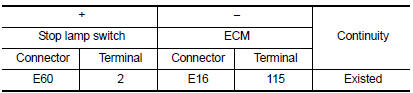
- Also check harness for short to ground.
Is the inspection result normal? YES >> Check intermittent incident. Refer to GI-39, "Intermittent Incident".
NO >> Repair or replace error-detected parts.
Component Inspection (Stop Lamp Switch)
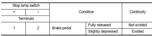
1.CHECK STOP LAMP SWITCH-I
- Turn ignition switch OFF.
- Disconnect stop lamp switch harness connector.
- Check the continuity between stop lamp switch terminals under the following conditions.
Is the inspection result normal? YES >> INSPECTION END
NO >> GO TO 2.
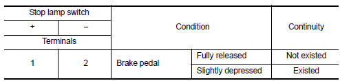
2.CHECK STOP LAMP SWITCH-II
- Adjust stop lamp switch installation. Refer to BR-15, "Adjustment".
- Check the continuity between stop lamp switch terminals under the following conditions.
Is the inspection result normal? YES >> INSPECTION END
NO >> Replace stop lamp switch. Refer to BR-22, "Exploded View".
 P1800 Intake manifold tuning valve
DTC Logic
DTC DETECTION LOGIC
DTC No.
CONSULT screen terms
(Trouble diagnosis content)
DTC detecting condition
Possible cause
P1800
VIAS S/V-1
(Variable intake air ...
 P2004 Intake manifold runner control valve
DTC Logic
DTC DETECTION LOGIC
DTC No.
CONSULT screen terms
(Trouble diagnosis content)
DTC detecting condition
Possible cause
P2004
TUMBLE CONT/V
(Intake manifold r ...
Other materials:
Diagnosis system (bcm) (with intelligent
key system)
Common item
Common item : consult function (bcm -
common item)
APPLICATION ITEM
CONSULT performs the following functions via CAN communication with BCM.
Direct Diagnostic Mode
Description
ECU identification
The BCM part number is displayed.
Self Diagnostic Result
...
System
Interior room lamp control system
INTERIOR ROOM LAMP CONTROL SYSTEM : System Diagram
WITH INTELLIGENT KEY
WITHOUT INTELLIGENT KEY
INTERIOR ROOM LAMP CONTROL SYSTEM : System Description
OUTLINE
Interior room lamp* is controlled by the interior room lamp timer
control function of t ...
Removal and installation
Ecm
Exploded View
ECM bracket
ECM
Engine mounting insulator bracket
Removal and Installation
CAUTION:
Perform ADDITIONAL SERVICE WHEN REPLACING ECM. Refer to EC-135, "Work
Procedure".
REMOVAL
Remove battery. Refer to PG-50, "Removal and Installation (Battery)& ...
