Nissan Sentra Service Manual: System
Interior room lamp control system
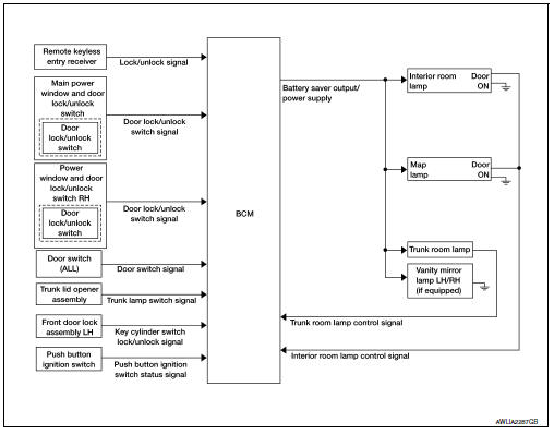
INTERIOR ROOM LAMP CONTROL SYSTEM : System Diagram
WITH INTELLIGENT KEY
WITHOUT INTELLIGENT KEY
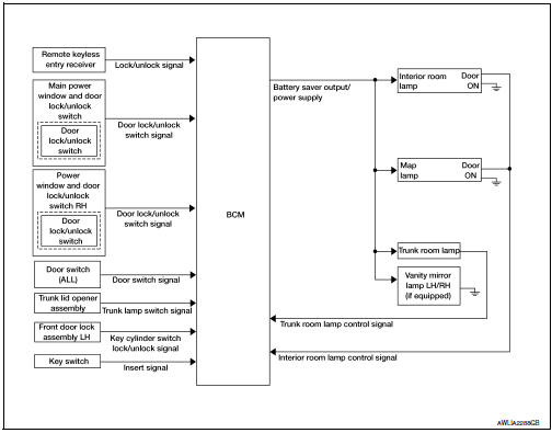
INTERIOR ROOM LAMP CONTROL SYSTEM : System Description
OUTLINE
- Interior room lamp* is controlled by the interior room lamp timer control function of the BCM.
- Trunk room lamp is controlled by the trunk room lamp control function of the BCM.
The timer control functions of the BCM activate based on inputs from the key cylinder lock/unlock switch LH, the door switches, the key switch and door lock/unlock switches.
*Interior room lamp and map lamp (when lamp switch is in DOOR position).
ROOM LAMP TIMER OPERATION
When the interior room lamp switch is in the DOOR position and when all conditions below are met, the BCM begins timer control (maximum 30 seconds) for interior room lamp ON/OFF.
- When the front door LH is unlocked with key fob, main power window and door lock/unlock switch, power window and door lock/unlock switch RH or front door lock assembly LH (key cylinder switch).
- When a door opens → closes and the push-button ignition switch is not pressed (with Intelligent Key).
- When a door opens → closes and the key is not inserted in the ignition switch (without Intelligent Key).
Timer control is cancelled under the following conditions.
- When the front door LH is locked with key fob, main power window and door lock/unlock switch, power window and door lock/unlock switch RH or front door lock assembly LH (key cylinder switch).
- A door is opened (door switch turns ON).
- Ignition switch is turned ON.
Interior lamp operational settings can be changed with the function setting of CONSULT.
INTERIOR LAMP BATTERY SAVER CONTROL
If an interior lamp is left ON and does not turn OFF even when the doors are closed, the BCM turns off power to the interior lamps automatically to save the battery 10 minutes after the ignition switch is turned OFF.
The BCM controls power and ground to all interior lamps.
After the battery saver system turns the lamps OFF, the lamps will illuminate again when
- a signal is received from a key fob, main power window and door lock/unlock switch, power window and door lock/unlock switch RH or when the front door lock assembly LH (key cylinder switch) is locked or unlocked
- a door is opened or closed
- the key is removed from or inserted into the ignition switch (without Intelligent Key).
The interior lamp battery saver control time period can be changed with the function setting of CONSULT.
Illumination control system
ILLUMINATION CONTROL SYSTEM : System Diagram
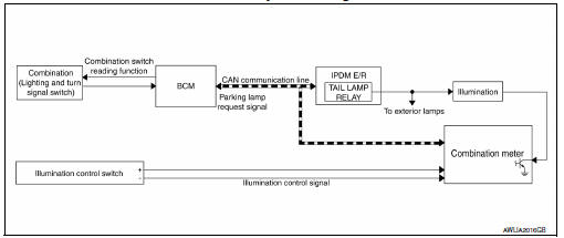
ILLUMINATION CONTROL SYSTEM : System Description
The illumination lamps operation is dependent upon the position of the combination switch (lighting and turn signal switch). When the combination switch (lighting and turn signal switch) is placed in the AUTO (if equipped and activated) or parking lamp position the BCM (body control module) receives input requesting the parking lamps to illuminate. This input is communicated to the IPDM E/R (intelligent power distribution module engine room) via the CAN communication lines. The CPU (central processing unit) of the IPDM E/R controls the tail lamp relay coil. When energized, this relay directs power to the parking and illumination lamps, which then illuminate.
BATTERY SAVER CONTROL
When the combination switch (lighting and turn signal switch) is in the AUTO (if equipped and activated) or parking lamp position and the ignition switch is turned from ON or ACC to OFF, the battery saver control feature is activated. Under this condition, the illumination lamps remain illuminated for 10 minutes unless the combination switch (lighting and turn signal switch) position is changed. If the combination switch (lighting and turn signal switch) position is changed, then the illumination lamps are turned off after a 30 second delay.
When the combination switch (lighting and turn signal switch) is turned from OFF to AUTO (if equipped and activated) or parking lamp position after illumination lamps have been turned off by the battery saver control, the illumination lamps illuminate again.
 Component parts
Component parts location
BCM (view with instrument panel removed)
Key switch
(without Intelligent Key)
Push-button ignition switch
(with Intelligent Key)
IPDM E/R
Illumination con ...
 Diagnosis system (bcm) (with intelligent key system)
Common item
COMMON ITEM : CONSULT Function (BCM - COMMON ITEM)
APPLICATION ITEM
CONSULT performs the following functions via CAN communication with BCM.
Direct Diagnostic Mode
Descriptio ...
Other materials:
Precaution for Work
When removing or disassembling each component, be careful not to damage
or deform it. If a component
may be subject to interference, be sure to protect it with a shop cloth.
When removing (disengaging) components with a screwdriver or similar
tool, be sure to wrap the component
with a ...
Squeak and rattle trouble diagnoses
Work Flow
Customer interview
Interview the customer if possible, to determine the conditions that exist
when the noise occurs. Use the diagnostic
worksheet during the interview to document the facts and conditions when the
noise occurs and any
customer's comments; refer to rf-37, "d ...
Dlc branch line circuit
Diagnosis procedure
1.Check connector
Turn the ignition switch off.
Disconnect the battery cable from the negative terminal
Check the terminals and connectors of the data link connector for damage,
bend and loose connection
(connector side and harness side).
Is the inspection result ...
