Nissan Sentra Service Manual: Strg branch line circuit
Diagnosis Procedure
1.Check connector
- Turn the ignition switch off
- Disconnect the battery cable from the negative terminal.
- Check the terminals and connectors of the steering angle sensor for damage, bend and loose connection (unit side and connector side).
Is the inspection result normal? Yes >> go to 2.
No >> repair the terminal and connector
2.Check harness for open circuit
- Disconnect the connector of steering angle sensor.
- Check the resistance between the steering angle sensor harness connector terminals.
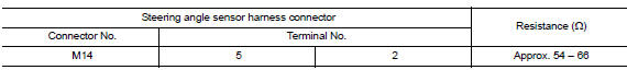
Is the measurement value within the specification? YES >> GO TO 3.
NO >> Repair the steering angle sensor branch line.
3.Check power supply and ground circuit
Check the power supply and the ground circuit of the steering angle sensor. Refer to brc-44, "wiring diagram".
Is the inspection result normal? Yes (present error)>>replace the steering angle sensor. Refer to brc-113, "removal and installation".
Yes (past error)>>error was detected in the steering angle sensor branch line.
No >> repair the power supply and the ground circuit.
 M&a branch line circuit
Diagnosis procedure
1.Check connector
Turn the ignition switch off.
Disconnect the battery cable from the negative terminal.
Check the terminals and connectors of the combination meter for da ...
 AV branch line circuit
Diagnosis procedure
1.Check connector
Turn the ignition switch off
Disconnect the battery cable from the negative terminal.
Check the terminals and connectors of the av control unit for damag ...
Other materials:
P0172 Fuel injection system function
DTC Logic
DTC DETECTION LOGIC
With the Air/Fuel Mixture Ratio Self-Learning Control, the actual mixture
ratio can be brought closely to the
theoretical mixture ratio based on the mixture ratio feedback signal from the
A/F sensors 1. The ECM calculates
the necessary compensation to correct th ...
Washing
Wash dirt off with a wet sponge and plenty of
water. Clean the vehicle thoroughly using a mild
soap, a special vehicle soap or general purpose
dishwashing liquid mixed with clean, lukewarm
(never hot) water.
CAUTION
Do not use car washes that use acid in
the detergent. Some car washes, es ...
Heating and cooling unit assembly
Exploded view
With air conditioning
Defroster seal
Center ventilator seal
Upper distribution module
Side ventilator seal (LH)
Blower motor
Blower unit
Intake door motor
Power transistor
Power transistor wiring harness
Front floor duct (lh)
Vent and defroster linkage
Mo ...
