Nissan Sentra Service Manual: P2014, P2016, P2017, P2018 Intake manifold runner control valve position sensor
DTC Logic
DTC DETECTION LOGIC
NOTE:
If DTC P2014, P2016, P2017 or P2018 is displayed with DTC P0643, first perform the trouble diagnosis for DTC P0643. Refer to EC-353, "DTC Logic".
| DTC No. | CONSULT screen terms (Trouble diagnosis content) | DTC detecting condition | Possible cause |
| P2014 | IN/MANIFOLD RUNNER POS SEN B1 (Intake manifold runner position sensor/ switch circuit bank 1) | An excessively low voltage from the sensor is sent to ECM. |
|
| P2016 | IN/MANIFOLD RUNNER POS SEN B1 (Intake manifold runner position sensor/ switch circuit low bank 1) | ||
| P2017 | IN/MANIFOLD RUNNER POS SEN B1 (Intake manifold runner position sensor/ switch circuit high bank 1) | An excessively high voltage from the sensor is sent to ECM. | |
| P2018 | IN/MANIFOLD RUNNER POS SEN B1 (Intake manifold runner position sensor/ switch circuit intermittent bank 1) |
DTC CONFIRMATION PROCEDURE
1.PRECONDITIONING
If DTC Confirmation Procedure has been previously conducted, always perform the following before conducting the next test.
- Turn ignition switch OFF and wait at least 10 seconds.
- Turn ignition switch ON.
- Turn ignition switch OFF and wait at least 10 seconds.
TESTING CONDITION:
Before performing the following procedure, confirm that battery voltage is more than 11 V at idle.
>> GO TO 2.
2.PERFORM DTC CONFIRMATION PROCEDURE
- Start engine and let it idle for 10 seconds.
- Check 1st trip DTC.
Is 1st trip DTC detected? YES >> Proceed to EC-416, "Diagnosis Procedure".
NO >> INSPECTION END
Diagnosis Procedure
1.CHECK INTAKE MANIFOLD RUNNER CONTROL VALVE POSITION SENSOR POWER SUPPLY
- Turn ignition switch OFF.
- Disconnect intake valve manifold runner control valve position sensor harness connector.
- Turn ignition switch ON.
- Check the voltage between intake valve manifold runner control valve position sensor harness connector.
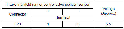
Is the inspection result normal? YES >> GO TO 6.
NO >> GO TO 2.
2.CHECK INTAKE MANIFOLD RUNNER CONTROL VALVE POSITION SENSOR POWER SUPPLY CIRCUIT
Check the voltage between intake valve manifold runner control valve position sensor harness connector and ground.
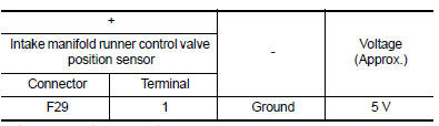
Is the inspection result normal? YES >> GO TO 4.
NO >> GO TO 3.
3.CHECK SENSOR POWER SUPPLY 2 CIRCUIT
Check sensor power supply 2 circuit. Refer to EC-444, "Diagnosis Procedure".
Is inspection result normal? YES >> Perform the trouble diagnosis for power supply circuit.
NO >> Repair or replace error-detected parts.
4.CHECK ECM GROUND CIRCUIT
- Turn ignition switch OFF.
- Disconnect ECM harness connector.
- Check the continuity between ECM harness connector and ground.
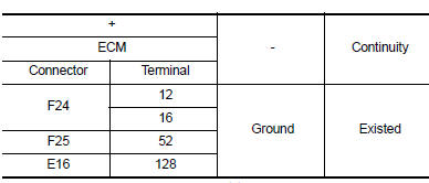
- Also check harness for short to power.
Is the inspection result normal? YES >> Check intermittent incident. Refer to GI-39, "Intermittent Incident".
NO >> Repair or replace error-detected parts.
5.CHECK INTAKE MANIFOLD RUNNER CONTROL VALVE POSITION SENSOR GROUND CIRCUIT
- Turn ignition switch OFF.
- Disconnect ECM harness connector.
- Check the continuity between intake manifold runner control valve position sensor harness connector and ECM harness connector.
- Also check harness for short to power.
Is the inspection result normal? YES >> GO TO 6.
NO >> Repair or replace error-detected parts.
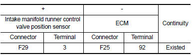
6.CHECK INTAKE MANIFOLD RUNNER CONTROL VALVE POSITION SENSOR INPUT SIGNAL CIRCUIT
- Check the continuity between intake manifold runner control valve position sensor harness connector and ECM harness connector.
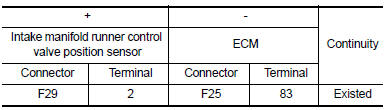
- Also check harness for short to ground and to power.
Is the inspection result normal? YES >> GO TO 7.
NO >> Repair or replace error-detected parts.
7.CHECK INTERMITTENT INCIDENT
Perform GI-39, "Intermittent Incident".
Is the inspection result normal? YES >> Replace intake manifold assembly. Refer to EM-27, "Exploded View".
NO >> Repair or replace error-detected parts.
 P2004 Intake manifold runner control valve
DTC Logic
DTC DETECTION LOGIC
DTC No.
CONSULT screen terms
(Trouble diagnosis content)
DTC detecting condition
Possible cause
P2004
TUMBLE CONT/V
(Intake manifold r ...
 P2096, P2097 A/F Sensor 1
DTC Logic
DTC DETECTION LOGIC
DTC No.
CONSULT screen terms
(Trouble diagnosis content)
DTC detecting condition
Possible Cause
P2096
POST CAT FUEL TRIM SYS B1
(Post ...
Other materials:
Rear door glass
Removal and Installation
REMOVAL
NOTE:
LH rear door panel shown; RH similar.
Remove the rear door finisher. Refer to INT-19, "Removal and
Installation".
Remove the vapor barrier.
CAUTION:
Use care to not damage or tear vapor barrier during removal.
Remove the rear door ...
Chassis and body maintenance
In-cabin microfilter
In-cabin microfilter : removal and installation
REMOVAL
Remove the in-cabin microfilter cover.
CAUTION:
Before removing the in-cabin microfilter cover, let the vehicle rest
for at least 30 minutes.
Release the filter cover tab (A), then pull the bottom of the in- ...
Changing engine oil filter
Park the vehicle on a level surface and apply
the parking brake.
Turn the engine off.
Place a large drain pan under the oil filter C .
Loosen the oil filter with an oil filter wrench
by turning it counterclockwise. Then remove
the oil filter by turning it by hand.
CAUTION
Be c ...
