Nissan Sentra Service Manual: Chassis and body maintenance
In-cabin microfilter
In-cabin microfilter : removal and installation
REMOVAL
- Remove the in-cabin microfilter cover.
CAUTION:
Before removing the in-cabin microfilter cover, let the vehicle rest for at least 30 minutes.
- Release the filter cover tab (A), then pull the bottom of the in-cabin microfilter cover outwards.
- Pull down the in-cabin microfilter cover to disengage the hook at the top, then remove the in-cabin microfilter cover.
- Remove the in-cabin microfilter.
INSTALLATION
Installation is in the reverse order of removal.
CAUTION:
After installation, check that the in-cabin microfilter cover is securely fastened to the heating and cooling unit assembly.
Exhaust system
Exhaust system : checking exhaust system
Check the exhaust pipes, muffler, and mounting components for incorrect attachment, leaks, cracks, damage, or deterioration.
M/t oil
M/T OIL : Inspection
OIL LEAKAGE
Make sure that gear oil is not leaking from transaxle or around it.
OIL LEVEL
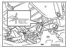
- Remove filler plug (1) and gasket from transaxle case.
- Check the oil level from filler plug mounting hole as shown.
CAUTION:
Do not start engine while checking oil level.
- Set a gasket on filler plug and then install it to transaxle case.
CAUTION:
Do not reuse gasket.
- Tighten filler plug to the specified torque. Refer to TM-30, "Exploded View".
CAUTION:
Do not overtighten the filler plug as this could cause the transaxle case to crack.
M/T OIL : Draining .
- Start engine and let it run to warm up transaxle.
- Stop engine. Remove drain plug (1) and gasket, using a suitable tool and then drain gear oil.
- Set a gasket on drain plug and install it to clutch housing, using a suitable tool.
CAUTION:
Do not reuse gasket.
- Tighten drain plug to the specified torque. Refer to TM-30, "Exploded View".
CAUTION:
Do not overtighten the filler plug as this could cause the transaxle case to crack.
M/T OIL : Refilling
- Remove filler plug (1) and gasket from transaxle case.
- Fill with new gear oil until oil level reaches the specified limit at filler plug mounting hole as shown.
Oil grade and viscosity : Refer to MA-11, "Fluids and Lubricants".
Oil capacity : Refer to MA-11, "Fluids and Lubricants".
- After refilling gear oil, check the oil level. Refer to MA-22, "M/T OIL : Inspection".
- Set a gasket on filler plug and then install it to transaxle case.
CAUTION:
Do not reuse gasket.
- Tighten filler plug to the specified torque. Refer to TM-30, "Exploded View".
CAUTION:
Do not overtighten the filler plug as this could cause the transaxle case to crack.
Cvt fluid
CVT FLUID : Inspection
FLUID LEAKAGE
- Check transaxle surrounding area (oil seal and plug etc.) for fluid leakage.
- If anything is found, repair or replace damaged parts and adjust CVT fluid level. Refer to MA-25, "CVT FLUID : Adjustment".
CVT FLUID : Replacement
Recommended CVT fluid and fluid capacity : Refer to TM-288, "General Specification".
CAUTION:
- Use only recommended CVT fluid. Using transmission fluid other than recommended CVT fluid will damage the CVT, which is not covered by the warranty.
- Always use shop paper. Do not use shop cloth.
- Replace a drain plug gasket with new ones at the final stage of the operation when installing.
- Use caution when looking into the drain hole as there is a risk of dripping fluid entering the eye.
- After replacement, always perform CVT fluid leakage check.
- Select “Data Monitor” in “TRANSMISSION” using CONSULT.
- Select “FLUID TEMP” and confirm that the CVT fluid temperature is 40°C (104°F) or less.
- Check that the selector lever is in the “P” position, then completely engage the parking brake.
- Lift up the vehicle.
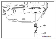
- Remove the drain plug and overflow tube and drain the CVT fluid from the oil pan. Refer to TM-266, "Exploded View".
- Install the charging pipe set (KV311039S0) (A) into the drain hole.
CAUTION:
Tighten the charging pipe by hand.
- Install the ATF changer hose (B) to the charging pipe.
CAUTION:
Press the ATF changer hose all the way onto the charging pipe until it stops.
- Fill approximately 3 liter (2-5/8 lmp qt) of the CVT fluid.
- Remove the ATF changer hose and charging pipe, then install the drain plug.
NOTE:
Perform this work quickly because CVT fluid leaks.
- Lift down the vehicle.
- Start the engine.
- While depressing the brake pedal, shift the selector lever to the entire position from “P” to “L”, and shift it to the “P” position.
NOTE:
Hold the lever at each position for 5 seconds.
Check that the CONSULT “Data monitor” in “FLUID TEMP” is 35°C (95°F) to 45°C (113°F).
- Stop the engine.
- Lift up the vehicle.
- Remove the drain plug, and then drain CVT fluid from oil pan.
- Repeat steps 6 to 16 (one time).
- Install the overflow tube. Refer to TM-266, "Exploded View".
CAUTION:
Be sure to tighten to the specified torque. If it is not tightened to the specified torque, the tube may be damaged.
- Install the charging pipe set (KV311039S0) (A) into the drain hole.
CAUTION:
Tighten the charging pipe by hand.
- Install the ATF changer hose (B) to the charging pipe.
CAUTION:
Press the ATF changer hose all the way onto the charging pipe until it stops.
- Fill approximately 3 liter (2-5/8 lmp qt) of the CVT fluid.
- Remove the ATF changer hose and charging pipe, then install the drain plug.
NOTE:
Perform this work quickly because CVT fluid leaks.

- Lift down the vehicle.
- Start the engine.
- While depressing the brake pedal, shift the selector lever to the entire position from “P” to “L”, and shift it to the “P” position.
NOTE:
Hold the lever at each position for 5 seconds.
- Check that the CONSULT “Data monitor” in “FLUID TEMP” is 35°C (95°F) to 45°C (113°F).
- Lift up the vehicle.
- Remove the drain plug and confirm that the CVT fluid is drained from the overflow tube.
CAUTION:
Perform this work with the vehicle idling.
NOTE:
If the CVT fluid is not drained, refer to “Adjustment” and refill with the CVT fluid.
- When the flow of CVT fluid slows to a drip, tighten the drain plug to the specified torque. Refer to TM-266, "Exploded View".
CAUTION:
Do not reuse drain plug gasket.
- Lift down the vehicle.
- Select “Work Support” in “TRANSMISSION” using CONSULT.
- Select “CONFORM CVTF DETERIORTN”.
- Touch “Erase”.
- Stop the engine.
CVT FLUID : Adjustment
Recommended CVT fluid and fluid capacity : Refer to TM-288, "General Specification".
CAUTION:
- Use only recommended CVT fluid. Using transmission fluid other than recommended CVT fluid will damage the CVT, which is not covered by the warranty.
- During adjustment of the CVT fluid level, check CONSULT so that the oil temperature may be maintained from 35 to 45В°C (95 to 113В°F).
- Use caution when looking into the drain hole as there is a risk of dripping fluid entering the eye.
- Check that the selector lever is in the “P” position, then completely engage the parking brake.
- Start the engine
- Adjust the CVT fluid temperature to be approximately 40В°C (104В°F).
NOTE:
The CVT fluid is largely affected by temperature. Therefore be sure to use CONSULT and check the “FLUID TEMP” under “TRANSMISSION” in “Data Monitor” while adjusting.
- While depressing the brake pedal, shift the selector lever to the entire position from “P” to “L”, and shift it to the “P” position.
NOTE:
Hold the lever at each position for 5 seconds.
- Lift up the vehicle
- Check that there is no CVT fluid leakage.
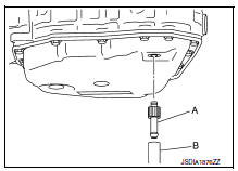
- Remove the drain plug. Refer to TM-266, "Exploded View".
- Install the charging pipe set (KV311039S0) (A) into the drain plug hole.
CAUTION:
Tighten the charging pipe by hand.
- Install the ATF changer hose (B) to the charging pipe.
CAUTION:
Press the ATF changer hose all the way onto the charging pipe until it stops.
- Fill approximately 0.5 liter (1/2 lmp qt) of the CVT fluid.
- Remove the ATF changer hose from the charging pipe, and check that the CVT fluid drains out from the charging pipe. If it does not drain out, perform charging again.
CAUTION:
Perform this work with the vehicle idling.
- When the flow of CVT fluid slows to a drip, remove the charging pipe from the oil pan.
- Tighten the drain plug to the specified torque. Refer to TM-266, "Exploded View".
CAUTION:
Do not reuse drain plug gasket.
- Lift down the vehicle.
- Stop the engine.
Wheels
Wheels : inspection
ALUMINUM WHEEL
- Check tires for wear and improper inflation.
- Check wheels for deformation, cracks and other damage. If deformed, remove wheel and check wheel runout.
- Remove tire from aluminum wheel and mount wheel on a balancer machine.
- Set dial indicator as shown.
- Check runout, if runout value exceeds the limit, replace aluminum wheel.
Limit
Lateral Deflection (A) Refer to WT-54, "Road Wheel".
Radial Deflection (B) Refer to WT-54, "Road Wheel".
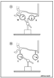
STEEL WHEEL
- Check tires for wear and improper inflation.
- Check wheels for deformation, cracks and other damage. If deformed, remove wheel and check wheel runout.
- Remove tire from steel wheel and mount wheel on a balancer machine.
- Set two dial indicators as shown.
- Set each dial indicator to "0".
- Rotate wheel and check dial indicators at several points around the circumference of the wheel.
- Calculate runout at each point as shown below.
Lateral deflection (A) = (W+X)/2
Radial deflection (B) = (Y+Z)/2
- Select maximum positive runout value and the maximum negative
value.
Add the two values to determine total runout.
In case a positive or negative value is not available, use the maximum value (negative or positive) for total runout.
If the total runout value exceeds the limit, replace steel wheel.
Limit
Lateral Deflection (A) Refer to WT-54, "Road Wheel".
Radial Deflection (B) Refer to WT-54, "Road Wheel".
Wheels : adjustment
BALANCING WHEELS (ADHESIVE WEIGHT TYPE)
Preparation Before Adjustment
Remove inner and outer balance weights from the road wheel. Using releasing agent, remove double-faced adhesive tape from the road wheel.
CAUTION:
- Be careful not scratch the road wheel during removal.
- After removing double-faced adhesive tape, wipe clean all traces of releasing agent from the road wheel.
Wheel Balance Adjustment
- If a balancer machine has an adhesive weight mode setting, select the
adhesive weight mode setting and
skip Step 2. below. If a balancer machine only has the clip-on (rim flange)
weight mode setting, follow Step 2.
to calculate the correct size adhesive weight.
- Set road wheel on balancer machine using the center hole as a guide. Start the balancer machine.
- For balancer machines that only have a clip-on (rim flange) weight mode setting, follow this step to calculate the correct size adhesive weight to use. When inner and outer imbalance values are shown on the balancer machine indicator, multiply outer imbalance value by 5/3 (1.67) to determine balance weight that should be used. Select the outer balance weight with a value closest to the calculated value above and install in to the designated outer position of, or at the designated angle in relation to the road wheel.
- Indicated imbalance value × 5/3 (1.67) = balance weight to be installed
Calculation example:
23 g (0.81 oz) × 5/3 (1.67) = 38.33 g (1.35 oz) ⇒ 40 g (1.41 oz) balance weight (closer to calculated balance weight value)
NOTE:
Note that balance weight value must be closer to the calculated balance weight value.
Example:
37.4 ⇒ 35 g (1.23 oz) 37.5 ⇒ 40 g (1.41 oz)
- Install balance weight in the position shown.
CAUTION:
- Do not install the inner balance weight before installing the outer balance weight.
- Before installing the balance weight, be sure to clean the mating surface of the road wheel.
- When installing balance weight (1) to road wheel, set it into the grooved area (A) on the inner wall of the road wheel as shown so that the balance weight center (B) is aligned with the balancer machine indication position (angle) (C).
CAUTION:
- Always use Genuine NISSAN adhesive balance weights.
- Balance weights are non-reusable; always replace with new ones.
- Do not install more than three sheets of balance weight.
CAUTION:
- Always use Genuine NISSAN adhesive balance weights.
- Balance weights are non-reusable; always replace with new ones.
- Do not install more than three sheets of balance weight.
- If calculated balance weight value exceeds 50 g (1.76 oz), install two balance weight sheets in line with each other as shown.
CAUTION:
Do not install one balance weight sheet on top of another.
- Start balancer machine again.
- Install balance weight on inner side of road wheel in the balancer machine indication position (angle).
CAUTION:
Do not install more than two balance weights.
- Start balancer machine. Make sure that inner and outer residual imbalance values are 5 g (0.18 oz) each or below.
- If either residual imbalance value exceeds 5 g (0.18 oz), repeat installation procedures.
Allowable imbalance Refer to WT-54, "Road Wheel".
Tire rotation
- Follow the maintenance schedule for tire rotation service intervals.
Refer to MA-5, "Explanation of General Maintenance".
- When installing the wheel, tighten wheel nuts to the specified torque.
Caution:
- Do not include the t-type spare tire when rotating the tires.
- When installing wheels, tighten them diagonally by dividing the work two to three times in order to prevent the wheels from developing any distortion.
- Be careful not to tighten wheel nut at torque exceeding the criteria for preventing strain of disc rotor.
- Use nissan genuine wheel nuts for aluminum wheels.
Wheel nut tightening torque refer to wt-54, "road wheel".
Brake fluid level and leaks
Brake fluid level and leaks : inspection
Brake fluid level
- Make sure that the brake fluid level in the reservoir tank is between the max and min lines.
- Visually check around the reservoir tank for brake fluid leakage.
- If the brake fluid level is excessively low, check the brake system for leakage.
- If brake warning lamp remains illuminated after parking brake pedal is released, check the brake system for brake fluid leakage.
Brake line
- Check brake line (tubes and hoses) for cracks, deterioration or other damage. Replace any damaged parts.
- Check for brake fluid leakage by depressing brake pedal under a force of 785 n (80 kg-f, 177 lb-ft) for approximately 5 seconds while engine is running.
Caution:
If brake fluid leakage occurs around joints, retighten or replace damaged parts as necessary.
Brake lines and cables
BRAKE LINES AND CABLES : Inspection
- Check brake fluid lines and parking brake cables for improper attachment, leaks, chafing, abrasions, deterioration, etc.
Brake fluid
BRAKE FLUID : Drain and Refill
Caution:
- Do not spill or splash brake fluid on painted surfaces. Brake fluid may damage paint. If brake fluid is splashed on painted areas, wash it away with water immediately.
- Prior to repair, turn the ignition switch off, disconnect the abs actuator and electric unit (control unit) connector or negative battery terminal. Refer to pg-50, "exploded view".
- Refill brake system with new brake fluid. Refer to ma-11, "fluids and lubricants".
- Do not reuse drained brake fluid.
Draining
- Turn ignition switch OFF and disconnect ABS actuator and electric unit (control unit) connector or negative battery terminal. Refer to PG-50, "Exploded View".
- Connect a vinyl tube to bleeder valve
- Depress brake pedal, loosen bleeder valve, and gradually remove brake fluid.
Refilling
- Make sure no foreign material exists in the reservoir and refill with new brake fluid.
Caution:
Do not reuse drained brake fluid.
- Refill the brake system as follows:
- Depress the brake pedal.
- Loosen bleeder valve.
- Slowly depress brake pedal to 2/3 of the brake pedal full stroke.
- Tighten bleeder valve.
- Release brake pedal.
Repeat this operation at intervals of two or three seconds until all old brake fluid is discharged. Add new brake fluid to master cylinder reservoir sub tank frequently.
Caution:
Do not allow master cylinder reservoir to empty as this may cause damage to master cylinder internal components.
- Bleed the air out of the brake hydraulic system. Refer to br-17, "bleeding brake system".
Front disc brake
Front disc brake : inspection
Pad wear
Check brake pad thickness from an inspection hole on caliper body.
Check using a scale if necessary.
Wear limit thickness : refer to br-55, "front disc brake".
Front disc brake : inspection
Appearance
Check surface of disc rotor for uneven wear, cracks or damage. Replace if any abnormal conditions exist.
Runout
- Check the wheel bearing axial end play before the inspection. Refer to fax-6, "inspection".
- Secure the disc rotor to the wheel hub and bearing assembly with wheel nuts at two wheel nut locations.
- Inspect the runout with a dial gauge, measured at 10 mm (0.39 In) inside the disc edge.
Runout : refer to br-55, "front disc brake".
- Find the installation position with a minimum runout by shifting the disc rotor-to-wheel hub and bearing assembly installation position by one hole at a time if the runout exceeds the limit value.
- Refinish the disc rotor if the runout is outside the limit even after performing the above operation. When refinishing, use tool.
Tool number : 38-pfm90.5 ( — )
Thickness
Check the thickness of the disc rotor using a micrometer. Replace the disc rotor if the thickness is below the wear limit.
Wear thickness : refer to br-55, "front disc brake".
Thickness variation : refer to br-55, "front disc brake".
Front disc brake : brake burnishing
Caution:
- Burnish contact surfaces between brake pads and disc rotor according to the following procedure after refinishing the disc rotor, replacing brake pads or if a soft pedal occurs at very low mileage.
- Be careful of vehicle speed. Brakes do not operate firmly/securely until pads and disc rotor are securely seated.
- Only perform this procedure under safe road and traffic conditions. Use extreme caution.
- Drive the vehicle on straight, flat road.
- Depress the brake pedal until the vehicle stops.
- Release the brake pedal for a few minutes to allow the brake components to cool.
- Repeat steps 1 to 3 until pad and disc rotor are securely seated.
Rear drum brake
Rear drum brake : inspection
Inspection
Brake lining
- Check brake lining wear thickness (a). Check using a scale if necessary.
Lining wear thickness (a) : refer to br-55, "rear drum brake".
Rear drum brake : inspection
Inspection
Appearance
Check surface of brake drum for uneven wear, cracks and serious damage. Replace it if necessary. Refer to br-42, "removal and installation".
Brake drum inner diameter
Check inner diameter (b) of the brake drum using suitable tool.
Brake drum inner diameter (b) : refer to br-55, "rear drum brake".
Rear drum brake : brake burnishing
Caution:
- Burnish contact surfaces between brake drum and brake lining according to the following procedure after refinishing or replacing brake drum, or if a soft pedal occurs at very low mileage.
- Be careful of vehicle speed because the brake does not operate firmly/securely until brake drum and brake lining are securely fitted.
- Only perform this procedure under safe road and traffic conditions. Use extreme caution.
- Drive the vehicle on straight, flat road.
- Depress the brake pedal until the vehicle stops.
- Release the brake pedal for a few minutes to allow the brake components to cool.
- Repeat steps 1 to 3 until pad and disc rotor are securely seated.
Rear disc brake
Rear disc brake : inspection
Pad wear
Check pad thickness from an inspection hole on caliper body. Check using a scale if necessary.
Wear limit thickness : refer to br-55, "rear disc brake".
Rear disc brake : inspection
Apperance
Check surface of disc rotor for uneven wear, cracks or damage. Replace if any abnormal conditions exist.
Runout
- Check the wheel bearing axial end play before the inspection. Refer to rax-5, "inspection".
- Secure the disc rotor to the wheel hub and bearing assembly with wheel nuts at two wheel nut locations.
- Inspect the runout with a dial gauge, measured at 10 mm (0.39 In) inside the disc edge.
Runout : refer to br-55, "rear disc brake".
- Find the installation position with a minimum runout by shifting the disc rotor-to-wheel hub and bearing assembly installation position by one hole at a time if the runout exceeds the limit value.
- Refinish the disc rotor if the runout is outside the limit even after performing the above operation. When refinishing, use tool.
Tool number : 38-pfm90.5 ( — )
Thickness
Check the thickness of the disc rotor using a micrometer. Replace the disc rotor if the thickness is below the minimum thickness.
Minimum thickness : refer to br-55, "rear disc brake".
Thickness variation : refer to br-55, "rear disc brake".
Rear disc brake : brake burnishing
Caution:
- Burnish contact surfaces between brake pads and disc rotor according to the following procedure after refinishing the disc rotor, replacing brake pads or if a soft pedal occurs at very low mileage.
- Be careful of vehicle speed. Brakes do not operate firmly/securely until pads and disc rotor are securely seated.
- Only perform this procedure under safe road and traffic conditions. Use extreme caution.
- Drive the vehicle on straight, flat road.
- Depress the brake pedal until the vehicle stops.
- Release the brake pedal for a few minutes to allow the brake components to cool.
- Repeat steps 1 to 3 until pad and disc rotor are securely seated.
Steering gear and linkage
Steering gear and linkage : inspection
Inspection after disassembly
Boot
- Check boot for cracks. Replace if any damage is found.
Steering gear assembly housing
- Check steering gear assembly housing for damage and scratches. Replace if there are any abnormal conditions.
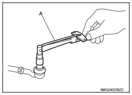
Outer socket and inner socket
- Ball joint swinging torque
- Hook a spring balance to the ball stud and inner socket measuring point (*) and pull the spring balance. Make sure that the spring balance reads the specified value when ball stud and inner socket start to move. Replace outer socket and inner socket if they are outside the specification.
Tool number : — (j-44372)
Swinging torque : refer to st-19, "power steering gear".
Ball joint rotating torque
- Make sure that the reading is within the following specified range using tool (a). Replace outer socket if the reading is outside the specification.
Tool number (a) : st3127s000 (j-25765-a) rotating torque : refer to st-19, "power steering gear".
Ball joint axial end play
- Apply an axial load of 490 n (50 kg, 111 lb.) To ball stud. Measuring the amount of stud movement using a dial gauge, make sure that the value is within specification. Replace outer socket (a) and inner socket (b) if the measured value is outside specification.
Axial end play : refer to st-19, "power steering gear".
Inspection after installation
- Check if steering wheel turns smoothly when it is turned several times fully to the end of the left and right.
- Check the steering wheel play, neutral position steering wheel, steering wheel turning force, and front wheel turning angle.
- Steering wheel play: Refer to ST-18, "Steering Wheel".
- Neutral position steering wheel, steering wheel turning force, and front wheel turning angle: refer to st-5, "inspection".
Axle and suspension parts
Axle and suspension parts : inspection
Check front and rear axle and suspension parts for excessive play, cracks, wear or other damage.
- Shake each wheel to check for excessive play.
- Check wheel bearings for smooth operation.
- Check axle and suspension nuts and bolts for looseness.
- Check strut (shock absorber) for oil leakage or other damage.
- Check suspension ball joint for grease leakage and ball joint dust cover for cracks or other damage.
Drive shaft
Drive shaft : inspection
Check the following items, and replace the part if necessary.
- Check drive shaft mounting point and joint for looseness and other damage.
Caution:
Replace entire drive shaft assembly when noise or vibration occurs from drive shaft.
- Check boot for cracks and other damage.
Locks, hinges and hood latch
LOCKS, HINGES AND HOOD LATCH : Lubricating
Seat belt, buckles, retractors, anchors and adjusters
SEAT BELT, BUCKLES, RETRACTORS, ANCHORS AND ADJUSTERS : Inspection
Caution:
- After any collision, inspect all seat belt assemblies, including
retractors and other attached hardware
(i.E. Anchor bolt, guide rail set). Nissan recommends to replace all seat
belt assemblies in use
during a collision, unless not damaged and properly operating after minor
collision.
Also inspect seat belt assemblies not in use during a collision, and replace if damaged or improperly operating.
Seat belt pre-tensioner should be replaced even if the seat belts are not in use during a frontal collision where the driver and passenger air bags are deployed.
- If any component of seat belt assembly is questionable, do not
repair.
Replace as seat belt assembly.
- If webbing is cut, frayed, or damaged, replace seat belt assembly.
- Do not oil tongue and buckle.
- Use only a genuine nissan seat belt assembly.
For details, refer to sb-5, "inspection" in the sb section.
- Check anchors for loose mounting.
- Check belts for damage.
- Check retractor for smooth operation.
- Check function of buckles and tongues when buckled and released.
 Engine maintenance
Drive belt
Drive belt : inspection
Alternator
Drive belt auto-tensioner
Crankshaft pulley
A/c compressor
Water pump
Drive belt
Possible use range
New drive belt range
Ndica ...
Other materials:
Symptom diagnosis
Engine does not start when intelligent key is inside of vehicle
Description
Engine does not start when push-button ignition switch is pressed while
carrying intelligent key.
Note:
Check that vehicle is under the condition shown in “conditions of
vehicle” before starting diagnos ...
Headlamp
Aiming adjustment
Preparation before adjusting
Before performing aiming adjustment, check the following:
Ensure all tires are inflated to correct pressure.
Place vehicle and screen on level surface.
Ensure there is no load in vehicle other than the driver (or equivalent
weight placed in ...
Wiring diagram
Sport mode system
Wiring diagram
...
