Nissan Sentra Service Manual: Engine maintenance
Drive belt
Drive belt : inspection
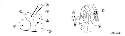
- Alternator
- Drive belt auto-tensioner
- Crankshaft pulley
- A/c compressor
- Water pump
- Drive belt
- Possible use range
- New drive belt range
- Ndicator
Warning:
Perform this step when engine is stopped.
- Check that the indicator of drive belt auto-tensioner is within the possible use range.
Note:
- Check the drive belt auto-tensioner indication when the engine is cold.
- When new drive belt is installed, the indicator should be within the new drive belt range.
- Visually check entire drive belt for wear, damage or cracks.
- If the indicator is out of the possible use range or belt is damaged, replace drive belt.
Drive belt : adjustment
Belt tension is not necessary, as it is automatically adjusted by drive belt auto-tensioner.
Engine coolant
Engine coolant : system inspection
Warning:
- Do not remove the radiator cap when the engine is hot. Serious burns could occur from high pressure engine coolant escaping from the radiator.
- Wrap a thick cloth around the cap. Slowly push down and turn it a quarter turn to allow built-up pressure to escape. Carefully remove the cap by pushing down and turning it all the way.
Checking cooling system hoses
Check hoses for the following:
- Improper attachment
- Leaks
- Cracks
- Damage
- Loose connections
- Chafing
- Deterioration
Checking reservoir level
- Check if the reservoir tank engine coolant level is within min to max when the engine is cool.
- Adjust engine coolant level if it is too much or too little.
Engine coolant : changing engine coolant
Warning:
To avoid being scalded, do not change the engine coolant when the engine is hot.
Wrap a thick cloth around cap and carefully remove the cap. First, turn the cap a quarter of a turn to release built-up pressure. Then push down and turn the cap all the way to remove.
Draining engine coolant
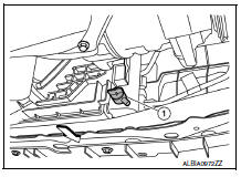
- Remove the engine under cover. Refer to ext-16, "exploded view".
- Open the radiator drain plug (1) at the bottom of the radiator and remove the radiator filler cap. This is the only step required when partially draining the cooling system (radiator only).
Caution:
- Do not spill engine coolant on the drive belt.
- Perform this step when the engine is cold.
- Follow this step for heater core removal/replacement only. Disconnect the upper heater hose at the engine side and apply moderate air pressure [103.46 Kpa (1.055 Kg/cm2, 15 psi) maximum air pressure] into the hose for 30 seconds to blow the excess engine coolant out of the heater core.
- When draining all of the engine coolant in the system, remove the reservoir tank and drain the engine coolant, then clean the reservoir tank before installation.
Caution:
- Do not allow the engine coolant to contact the drive belt.
- Perform this step when engine is cold.
- When draining all of the engine coolant in the system for engine removal or repair, remove the engine coolant drain plugs on the cylinder block.
- Check the drained engine coolant for contaminants such as rust,
corrosion or discoloration.
If the engine coolant is contaminated, flush the engine cooling system.
Refilling engine coolant
- Install the radiator drain plug. Install the reservoir tank and cylinder block drain plug, if removed for a total system drain or for engine removal or repair.
- The radiator must be completely empty of engine coolant and water.
- Apply sealant to the threads of the cylinder block drain plug. Use genuine high performance thread sealant or equivalent. Refer to ma-11, "fluids and lubricants".
Radiator drain plug : refer to co-15, "exploded view".
- If disconnected, reattach the upper radiator hose at the engine side.
- Set the vehicle heater controls to the full hot and heater on position. Turn the vehicle ignition on with the engine off as necessary to activate the heater mode.
- Install the tool by installing the radiator cap adapter onto the radiator neck opening. Then attach the gauge body assembly with the refill tube and the venturi assembly to the radiator cap adapter.
Tool number : kv991j0070 (j-45695)
- Insert the refill hose into the engine coolant mixture container that is placed at floor level. Make sure the ball valve is in the closed position.
- Use recommended engine coolant or equivalent.
Refer to ma-11, "fluids and lubricants" (united states and canada).
Engine coolant capacity (with reservoir tank) : refer to co-28, "periodical maintenance specification".
Caution:
Do not use any cooling system additives such as radiator sealer. Additives may clog the cooling system and cause damage to the engine, transmission and/or cooling system.
- Install an air hose to the venturi assembly, the air pressure must be within specification.
Compressed air supply pressure : 549 - 824 kpa (5.6 - 8.4 Kg/cm2, 80 - 119 psi)
Caution:
The compressed air supply must be equipped with an air dryer.
- The vacuum gauge will begin to rise and there will be an audible hissing noise. During this process open the ball valve on the refill hose slightly. Engine coolant will be visible rising in the refill hose. Once the refill hose is full of engine coolant, close the ball valve. This will purge any air trapped in the refill hose.
- Continue to draw the vacuum until the gauge reaches 28 inches of vacuum. The gauge may not reach 28 inches in high altitude locations, use the vacuum specifications based on the altitude above sea level.
Altitude above sea level vacuum gauge reading 0 - 100 m (328 ft) : 28 inches of vacuum 300 m (984 ft) : 27 inches of vacuum 500 m (1,641 ft) : 26 inches of vacuum 1,000 m (3,281 ft) : 24 - 25 inches of vacuum
- When the vacuum gauge has reached the specified amount, disconnect the air hose and wait 20 seconds to see if the system loses any vacuum. If the vacuum level drops, perform any necessary repairs to the system and repeat steps 6 - 8 to bring the vacuum to the specified amount. Recheck for any leaks.
- Place the engine coolant container (with the refill hose inserted) at
the same level as the top of the radiator.
Then open the ball valve on the refill hose so the engine coolant will be drawn up to fill the cooling system.
The cooling system is full when the vacuum gauge reads zero.
Caution:
Do not allow the engine coolant container to get too low when filling, to avoid air from being drawn into the cooling system.
- Remove the tool from the radiator neck opening.
- Fill the cooling system reservoir tank to the specified level and install the radiator cap. Run the engine to warm up the cooling system and top up the system as necessary.
- Install the engine under cover. Refer to ext-16, "exploded view".
Flushing cooling system
- Fill the radiator from the filler neck above the radiator upper hose and reservoir tank with clean water and reinstall the radiator filler cap.Ð Ñš
- Run the engine until it reaches normal operating temperature.
- Rev the engine two or three times under no-load.
- Stop the engine and wait until it cools down.
- Drain the water from the system. Refer to ma-14, "engine coolant : changing engine coolant".
- Repeat steps 1 through 5 until clear water begins to drain from the radiator.
Fuel lines
FUEL LINES : Inspection
Inspect fuel lines, fuel filler cap, and fuel tank for improper attachment, leakage, cracks, damage, loose connections, chafing or deterioration.
(A) : engine
(B) : Fuel line
(C) : Fuel tank
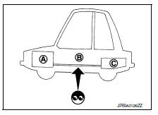
If necessary, repair or replace damaged parts.
Air cleaner filter
AIR CLEANER FILTER : Component
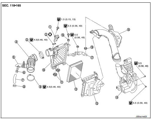
- Mass air flow sensor
- Mass air flow gasket
- Clamp
- Air duct (suction side)
- Resonator
- Clamp
- PCV hose
- Clamp
- Clamp
- Air cleaner cover
- Mounting rubber
- Air cleaner filter
- Air cleaner body
- Air duct inlet (lower)
- Air duct inlet (upper)
- Grommet
- Bracket
- Grommet
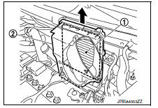
Air cleaner filter : removal and installation
REMOVAL
- Remove air duct inlet (upper) (1).
- Unhook the tabs (A) of both ends of the air cleaner cover.
- Remove the air cleaner filter (1) and air cleaner body (2) from the air cleaner cover.
- Remove the air cleaner filter from the air cleaner body.
INSTALLATION
Installation is in the reverse order of removal.
- Tabs shall be fixed after inserting air cleaner body protrusion to air cleaner case notch hole.
- Make sure that whether air cleaner body has been firmly installed by shaking it.
Air cleaner filter : inspection
INSPECTION AFTER REMOVAL
Examine with eyes that there is no stain, clogging, or damage on air cleaner element.
- Remove dusts (such as dead leafs) on air cleaner element surface and inside cleaner case.
- If clogging or damage is observed, replace the air cleaner element.
CAUTION:
Do not clean the viscous paper type air cleaner filter by blowing as there is risk of deterioration of its performance.
Engine oil
ENGINE OIL : Inspection
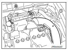
ENGINE OIL LEVEL
NOTE:
Before starting engine, put vehicle horizontally and check the engine oil level. If engine is already started, stop it and allow 10 minutes before checking.
- Pull out oil level gauge and wipe it clean.
- Insert oil level gauge and check that the engine oil level is within the range (A) shown.
- If engine oil is out of range, adjust it.
ENGINE OIL : Draining
WARNING:
- Be careful not to get burned, as engine oil may be hot.
- Prolonged and repeated contact with used engine oil may cause skin cancer. Try to avoid direct skin contact with used engine oil. If skin contact is made, wash thoroughly with soap or hand cleaner as soon as possible
- Warm up the engine, and check for engine oil leaks from engine components. Refer to MA-17, "ENGINE OIL : Inspection".
- Stop the engine and wait for 10 minutes.
- Loosen oil filler cap.
- Remove drain plug and then drain engine oil.
ENGINE OIL : Refilling
- Install drain plug with new drain plug washer. Refer to EM-33, "Exploded View".
CAUTION:
Be sure to clean drain plug and install with new drain plug washer.
Tightening torque : 34.3 NВ·m (3.5 kg-m, 25 ft-lb).
- Refill with new engine oil.
- Engine oil specification and viscosity: Refer to MA-11, "Engine Oil Recommendation".
- Engine oil capacity : Refer to LU-17, "Oil Capacity".
CAUTION:
- The refill capacity depends on the engine oil temperature and drain time. Use these specifications for reference only.
- Always use oil level gauge to determine the proper amount of engine oil in the engine.
- Warm up engine and check area around drain plug and oil filter for engine oil leaks.
- Stop engine and wait for 10 minutes.
- Check the engine oil level. Refer to MA-17, "ENGINE OIL : Inspection".
Oil filter
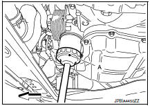
OIL FILTER : Removal and Installation
REMOVAL
- Remove engine under cover. Refer to EXT-16, "Exploded View".
- Drain engine oil. Refer to MA-18, "ENGINE OIL : Draining".
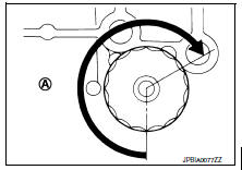
- Remove the oil filter using Tool (A) as shown.
 : Front
Tool number : KV10115801 (J-38956)
WARNING:
Be careful not to burn yourself, as the engine oil may be hot.
CAUTION:
- When removing, prepare a shop cloth to absorb any oil leaks or spills.
- Do not allow engine oil to adhere to the drive belts.
- Completely wipe off any oil that adheres to the engine and the vehicle.
- The oil filter is provided with a relief valve. Use a Genuine NISSAN oil filter or equivalent.
INSTALLATION
- Remove foreign materials adhering to the oil filter installation surface.
- Apply new engine oil to the oil seal contact surface of new oil filter.
- Screw oil filter manually until it touches the installation surface, then tighten it by 2/3 turn (A), or tighten to specification.
Oil filter : 18.0 NВ·m (1.8 kg-m, 13 ft-lb)
Tool number : KV10115801 (J-38956)
- Refill engine with new engine oil. Refer to MA-18, "ENGINE OIL : Refilling".
- Install engine under cover. Refer to EXT-16, "Exploded View".
OIL FILTER : Inspection
INSPECTION AFTER INSTALLATION
- Check the engine oil level. Refer to MA-17, "ENGINE OIL : Inspection".
- Start the engine, and check that there are no leaks of engine oil.
- Stop the engine and wait for 10 minutes.
- Check the engine oil level, and adjust the level. Refer to MA-17, "ENGINE OIL : Inspection".
Spark plug
Spark plug : removal and installation
REMOVAL
- Remove engine room cover. Refer to EM-24, "Exploded View".
- Remove ignition coil. Refer to EM-46, "Exploded View".
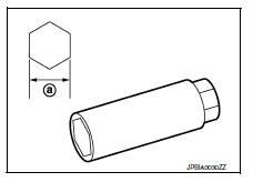
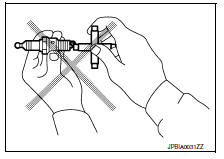
- Remove spark plug using suitable tool.
(a) : 14 mm (0.55 in)
CAUTION:
Do not drop or shock spark plug.
INSTALLATION
Installation is in the reverse order of removal.
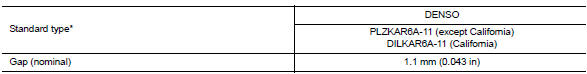
*: Always check with the Parts Department for the latest parts information.
CAUTION:
Always tighten the spark plug to specified torque to align the orientation of electrodes. The ground electrode of a genuine spark plug is positioned in the area of maximum ignitability by tightening to the specified torque. When replacing spark plugs, use genuine spark plugs of which the ground electrode is adjusted.
NOTE:
The ground electrode of the spark plug is positioned in the area of maximum ignitability to improve combustion efficiency in the cylinder, reduce CO2 (carbon dioxide) emission and improve fuel economy.
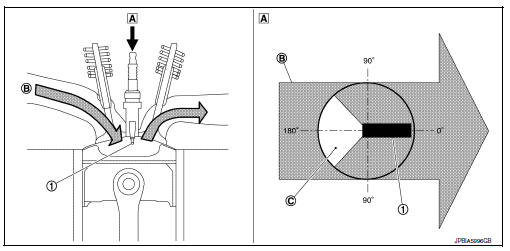
- Ground electrode of spark plug
- Top view
- Air-fuel mixture flow
- Poor ignitability region
Spark plug : inspection
INSPECTION AFTER REMOVAL
Use the standard type spark plug for normal condition.
Spark plug (Standard type) : Refer to EM-118, "Spark Plug".
CAUTION:
- Do not drop or shock spark plug.
- Do not use a wire brush for cleaning.
- If plug tip is covered with carbon, spark plug cleaner may be used.
Cleaner air pressure : Less than 588 kPa (6 kg/cm2, 85 psi)
Cleaning time : Less than 20 seconds
- Spark plug gap adjustment is not required between replacement intervals.
- Measure spark plug gap. when it exceeds the limit, replace
spark plug even if it is with in the specified replacement mileage.
Refer to EM-118, "Spark Plug".
Evap vapor lines
Evap vapor lines : inspection
- Visually inspect EVAP vapor lines for improper attachment and for cracks, damage, loose connections, chafing and deterioration.
- Inspect fuel tank filler cap vacuum relief valve for clogging, sticking, etc.
 Recommended fluids and lubricants
Fluids and lubricants
*1: For additional information, see “engine oil recommendation”.
*2: As an alternative to this recommended oil, sae 5w-30 conventional
petroleum based oil may ...
 Chassis and body maintenance
In-cabin microfilter
In-cabin microfilter : removal and installation
REMOVAL
Remove the in-cabin microfilter cover.
CAUTION:
Before removing the in-cabin microfilter cover, let the vehicle r ...
Other materials:
Variable voltage control system
CAUTION
Do not ground accessories directly to
the battery terminal. Doing so will bypass
the variable voltage control system
and the vehicle battery may not
charge completely.
Use electrical accessories with the engine
running to avoid discharging the
vehicle battery.
Your v ...
Installing top tether strap
WARNINGChild restraint anchorages are designed
to withstand only those loads imposed by
correctly fitted child restraints. Under no
circumstances are they to be used to attach
adult seat belts, or other items or
equipment to the vehicle. Doing so could
damage the child r ...
Basic inspection
DIAGNOSIS AND REPAIR WORKFLOW
Work Flow
OVERALL SEQUENCE
DETAILED FLOW
1.INTERVIEW CUSTOMER
Interview the customer to obtain as much information as possible about the
conditions and environment under
which the malfunction occurred.
>> GO TO 2.
2.SYMPTOM CHECK
Verify symptoms.
...
