Nissan Sentra Service Manual: Headlamp (lo) circuit
Description
The ipdm e/r (intelligent power distribution module engine room) controls the headlamp low relay based on inputs from the bcm over the can communication lines. When the headlamp low relay is energized, power flows through fuses 43 and 44, located in the ipdm e/r. Power then flows to the front combination lamps to the headlamp low beam.
Component function check
1.Check headlamp (lo) operation
 Without consult
- Start ipdm e/r auto active test. Refer to exl-24, "diagnosis description" (with intelligent key system) or exl-28, "diagnosis description" (without intelligent key system).
- Check that the headlamp is turned on.
Note:
HI/LO is repeated 1 second each when using the IPDM E/R auto active test.
 Consult
- Select external lamp of ipdm e/r active test item.
- While operating the test items, check that the headlamp is turned on.
Lo : headlamp on
Off : headlamp off
Is the inspection result normal? YES >> Headlamp (LO) is normal.
NO >> Refer to EXL-90, "Diagnosis Procedure".
Diagnosis procedure
Regarding Wiring Diagram information, refer to EXL-33, "Wiring Diagram".
1.Check headlamp (lo) fuses
- Turn the ignition switch off.
- Check that the following fuses are not blown.
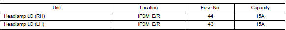
Is the fuse blown? YES >> Replace the fuse after repairing the affected circuit.
NO >> GO TO 2.
2.Check headlamp (lo) output voltage
 Consult
- Turn the ignition switch off.
- Disconnect the front combination lamp harness connector in question.
- Turn the ignition switch on.
- Select external lamp of ipdm e/r active test item.
- With external lamp on, check the voltage between the combination lamp connector and ground.


Is the inspection result normal? YES >> GO TO 4.
NO >> GO TO 3.
3.Check headlamp (lo) circuit for open
- Turn the ignition switch OFF.
- Disconnect ipdm e/r connector.
- Check continuity between the IPDM E/R harness connector and the front combination lamp harness connector.
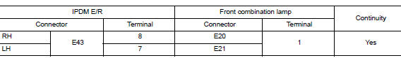
Is the inspection result normal? Yes >> replace ipdm e/r. Refer to pcs-30, "removal and installation" (with intelligent key system) or pcs-58, "removal and installation" (without intelligent key system).
No >> repair or replace the harness or connector.
Is the inspection result normal? Yes >> replace ipdm e/r. Refer to pcs-30, "removal and installation" (with intelligent key system) or pcs-58, "removal and installation" (without intelligent key system).
No >> repair or replace the harness or connector.
4.Check front combination lamp (lo) ground circuit
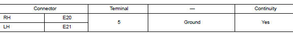
Is the inspection result normal? Yes >> inspect the headlamp bulb.
No >> repair or replace the harness or connector.
 Headlamp (hi) circuit
Description
The IPDM E/R (intelligent power distribution module engine room) controls the
headlamp high relay based on
inputs from the BCM over the CAN communication lines. When the headlamp high ...
 Daytime light relay circuit
Description
The bcm sends a daytime light request to the ipdm e/r via the can
communication lines. The power flows
through fuse 29 located in fuse block j/b to the daytime light relay coil. When
...
Other materials:
P060B ECM
DTC Logic
DTC DETECTION LOGIC
DTC No.
CONSULT screen terms
(Trouble diagnosis content)
DTC detecting condition
Possible cause
P060B
CONTROL MODULE
(Internal control module A/
D processing performance)
ECM internal analog/digital conversion processing
syst ...
P062F Eeprom
DTC Logic
DTC DETECTION LOGIC
DTC
CONSULT screen terms
(Trouble diagnosis content)
DTC detection condition
Possible causes
P062F
EEPROM
(Internal Control Module EEPROM
Error)
Flash ROM error is detected when turning ON
the ignition switch.
TC ...
P0604 ECM
DTC Logic
DTC DETECTION LOGIC
DTC No.
CONSULT screen terms
(Trouble diagnosis content)
DTC detecting condition
Possible cause
P0604
ECM
[Internal control module
random access memory
(RAM) error]
Malfunction in the internal RAM of ECM.
ECM
DTC CON ...
