Nissan Sentra Service Manual: Daytime light relay circuit
Description
The bcm sends a daytime light request to the ipdm e/r via the can communication lines. The power flows through fuse 29 located in fuse block j/b to the daytime light relay coil. When the ipdm e/r operates the daytime light relay, power is sent to the daytime lamps.
Diagnosis procedure
Regarding Wiring Diagram information, refer to EXL-38, "Wiring Diagram".
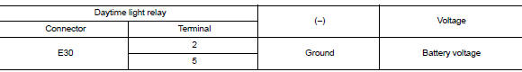
1.Check daytime light relay voltage supply
- Turn the ignition switch off.
- Remove the daytime light relay.
- Check the voltage between the daytime light relay harness connector and ground.
Is the inspection result normal? Yes >> go to 3.
No >> go to 2.
2.Check daytime light relay fuse
Check that the following fuses are not blown.

Is the fuse blown? Yes >> replace the blown fuse after repairing the affected circuit.
No >> repair or replace the harness or connector.
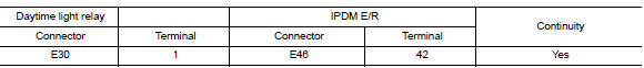
3.Check daytime light relay control circuit
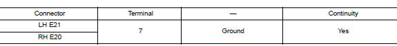
- Check continuity between the IPDM E/R harness connector and the daytime light relay harness connector.
- Check continuity between the daytime light relay harness connector and ground.

Is the inspection result normal? Yes >> go to 4.
No >> repair or replace the harness or connector.
4.Check daytime light relay
Check the daytime light relay. Refer to exl-93, "component inspection".
Is the inspection result normal? YES >> GO TO 5.
NO >> Replace relay.
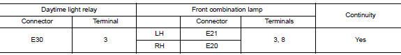
5.Check daytime light circuit (open or short to ground)
- Check continuity between the daytime light relay harness connector and the front combination lamp harness connector.
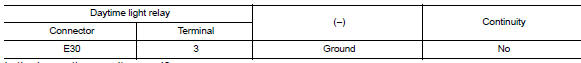
- Check continuity between the daytime light relay harness connector and ground.
Is the inspection result normal? Yes >> go to 6.
No >> repair or replace the harness or connector.
6.Check daytime light ground circuit for open
- Disconnect front combination lamp connector in question.
- Check continuity between the front combination lamp connector and ground.
Is the inspection result normal? Yes >> inspect daytime light bulb.
No >> repair or replace the harness or connector.
Component inspection
1. Check daytime light relay
- Turn ignition switch off.
- Remove daytime light relay.
- Check the continuity between daytime light relay terminals 3 and 5 when voltage is supplied between terminals 1 and 2.
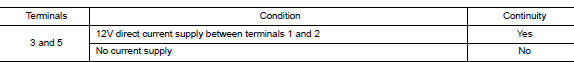
Is the inspection result normal? Yes >> inspection end.
No >> replace daytime light relay.
 Headlamp (lo) circuit
Description
The ipdm e/r (intelligent power distribution module engine room) controls the
headlamp low relay based on
inputs from the bcm over the can communication lines. When the headlamp low
...
 Front fog lamp circuit
Description
The ipdm e/r (intelligent power distribution module engine room) controls the
front fog lamp relay based on
inputs from the bcm over the can communication lines. When the front fog lam ...
Other materials:
Precautions on child restraints
WARNING
Failure to follow the warnings and instructions
for proper use and installation
of child restraints could result in
serious injury or death of a child or
other passengers in a sudden stop or
collision:
The child restraint must be used and
...
How to use the remote keyless entry function
The remote keyless entry function can operate all
door locks using the remote keyless function of
the Intelligent Key. The remote keyless function
can operate at a distance of 33 ft (10 m) away
from the vehicle. The operating distance depends
upon the conditions around the vehicle.
The remot ...
B0010, B0011 Passenger airbag module
Description
DTC B0010, B0011 PASSENGER AIR BAG MODULE
The passenger air bag module is dual stage and is wired to the air bag
diagnosis sensor unit. The air bag diagnosis
sensor unit will monitor for opens and shorts in detected lines to the passenger
air bag module.
PART LOCATION
Refer to S ...
