Nissan Sentra Service Manual: Main line between ipdm-e and dlc circuit
Diagnosis procedure
1.Check connector
- Turn the ignition switch off.
- Disconnect the battery cable from the negative terminal.
- Check the following terminals and connectors for damage, bend and loose connection (connector side and harness side).
- Harness connector E4
- Harness connector m2
Is the inspection result normal? Yes >> go to 2.
No >> repair the terminal and connector.
2.Check harness continuity (open circuit)
- Disconnect the following harness connectors.
- Ipdm e/r
- Harness connectors E4 and M2
- Check the continuity between the ipdm e/r harness connector and the harness connector.
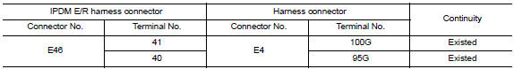
Is the inspection result normal? Yes >> go to 3.
No >> repair the main line between the ipdm e/r and the harness connector e4.
3.Check harness continuity (open circuit)
Check the continuity between the harness connector and the data link connector.
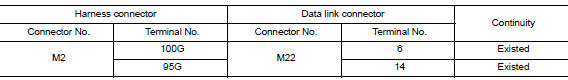
Is the inspection result normal? Yes (present error)>>check can system type decision again.
Yes (past error)>>error was detected in the main line between the ipdm e/r and the data link connector.
No >> repair the main line between the harness connector m2 and the data link connector.
 Can system (type 5)
Dtc/circuit diagnosis ...
 Main line between dlc and hvac circuit
Diagnosis procedure
1.Check harness continuity (open circuit)
Turn the ignition switch off.
Disconnect the battery cable from the negative terminal.
Disconnect the following harness connector ...
Other materials:
Combination meter
Reference Value
VALUES ON THE DIAGNOSIS TOOL
NOTE:
The following table includes information (items) inapplicable to this
vehicle. For information (items) applicable
to this vehicle, refer to CONSULT display items.
Note:
Some items are not available according to vehicle specificat ...
System
Meter system
Meter system : system diagram
Meter system : system description
COMBINATION METER
The combination meter receives signals from switches, sensors and modules to
control the following functions:
Speedometer/tachometer
Warning lamps
Indicator lamps
Meter illumination c ...
Low tire pressure warning lamp
Symptom Table
Low tire pressure warning lamp symptom chart
Note:
If tire pressure sensor wake-up operation is not completed for two or more
tire pressure sensors, the applicable
low tire pressure warning lamp blinking patterns are displayed continuously.
(Example: blinks once/off/bl ...
