Nissan Sentra Service Manual: P0078 EVT Control solenoid valve
DTC Logic
DTC DETECTION LOGIC
| DTC No. | CONSULT screen terms (Trouble diagnosis content) | DTC detecting condition | Possible cause |
| P0078 | EX V/T ACT/CIRC-B1 (Exhaust valve control solenoid circuit bank 1) | An improper voltage is sent to the ECM through exhaust valve timing control solenoid valve. |
|
DTC CONFIRMATION PROCEDURE
1.PRECONDITIONING
If DTC Confirmation Procedure has been previously conducted, always perform the following procedure before conducting the next test.
- Turn ignition switch OFF and wait at least 10 seconds.
- Turn ignition switch ON.
- Turn ignition switch OFF and wait at least 10 seconds.
>> GO TO2.
2.PERFORM DTC CONFIRMATION PROCEDURE
- Start engine and let it idle for 5 seconds.
- Check 1st trip DTC.
Is 1st trip DTC detected? YES >> Proceed to EC-183, "Diagnosis Procedure".
NO >> INSPECTION END
Diagnosis Procedure
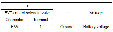
1.CHECK EXHAUST VALVE TIMING CONTROL SOLENOID VALVE POWER SUPPLY
- Turn ignition switch OFF
- Disconnect exhaust valve timing (EVT) control solenoid valve harness connector.
- Turn ignition switch ON.
- Check the voltage between exhaust valve timing control solenoid valve harness connector and ground.
Is the inspection result normal? YES >> GO TO 3.
NO >> GO TO 2.
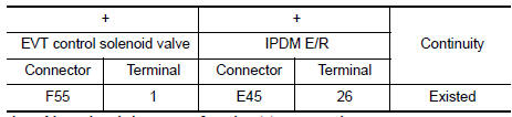
2.CHECK EXHAUST VALVE TIMING CONTROL SOLENOID VALVE POWER SUPPLY CIRCUIT
- Turn ignition switch OFF.
- Disconnect IPDM E/R harness connector.
- Check the continuity between EVT control solenoid valve harness connector and IPDM E/R harness connector.
- Also check harness for short to ground.
Is the inspection result normal? YES >> Perform the trouble diagnosis for power supply circuit.
NO >> Repair or replace error-detected parts.
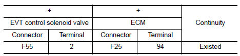
3.CHECK EXHAUST VALVE TIMING CONTROL SOLENOID VALVE GROUND CIRCUIT
- Turn ignition switch OFF.
- Disconnect ECM harness connector.
- Check the continuity between EVT control solenoid valve harness connector and ECM harness connector.
- Also check harness for short to ground and to power.
Is the inspection result normal? YES >> GO TO 4.
NO >> Repair or replace error-detected parts.
4.CHECK EXHAUST VALVE TIMING CONTROL SOLENOID VALVE
Check the exhaust valve timing control solenoid valve. Refer to EC-181, "Component Inspection (IVT Control Solenoid Valve)".
Is the inspection result normal? YES >> Check intermittent incident. Refer to GI-39, "Intermittent Incident".
NO >> Replace exhaust valve timing control solenoid valve. Refer to EM-49, "Removal and Installation".
Component Inspection (EVT Control Solenoid Valve)
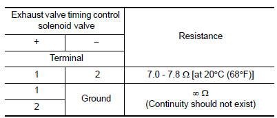
1.CHECK EXHAUST VALVE TIMING CONTROL SOLENOID VALVE-1
- Turn ignition switch OFF.
- Disconnect exhaust valve timing control solenoid valve harness connector.
- Check resistance between exhaust valve timing control solenoid valve terminals as per the following.
Is the inspection result normal? YES >> GO TO 2.
NO >> Replace exhaust valve timing control solenoid valve. Refer to EM-49, "Removal and Installation".
2.CHECK EXHAUST VALVE TIMING CONTROL SOLENOID VALVE-2
- Remove exhaust valve timing control solenoid valve. Refer to EM-48, "Exploded View".
- Provide 12 V DC between exhaust valve timing control solenoid valve terminals 1 and 2, and then interrupt it. Check that the plunger moves as shown in the figure.
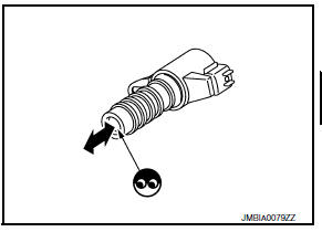
CAUTION:
Do not apply 12 V DC continuously for 5 seconds or more.
Doing so may result in damage to the coil in exhaust valve timing control solenoid valve.
NOTE:
Always replace O-ring when exhaust valve timing control solenoid valve is removed.
Is the inspection result normal? YES >> INSPECTION END
NO >> Replace exhaust valve timing control solenoid valve. Refer to EM-49, "Removal and Installation".
 P0075 IVT control solenoid valve
DTC Logic
DTC DETECTION LOGIC
DTC No.
CONSULT screen terms
(Trouble diagnosis content)
DTC detecting condition
Possible cause
P0075
INT/V TIM V/CIR-B1
(Intake valve ...
 P0101, P0102, P0103 MAF Sensor
DTC Logic
DTC DETECTION LOGIC
DTC No.
CONSULT screen terms
(Trouble diagnosis content)
DTC detecting condition
Possible cause
P0101
MAF SEN/CIRCUIT-B1
(Mass or volu ...
Other materials:
Sport mode control
SPORT MODE CONTROL : System Description
SYSTEM DIAGRAM
SYSTEM DESCRIPTION
SPORT mode that keeps high engine revolution and provides direct feel
and acceleration performance suitable
for driving on winding road.
ECM receives an SPORT mode signal from TCM via CAN communication and
...
Symptom diagnosis
Audio system
Symptom table
Related to audio
Related to hands-free phone
Before performing diagnosis, confirm that the cellular phone being used
by the customer is compatible with
the vehicle.
It is possible that a malfunction is occurring due to a version change
of the phone ...
Manual control
While using the Voice Recognition system, it is
possible to select menu options by using the
steering wheel controls instead of speaking voice
commands. The manual control mode does not
allow dialing a phone number by digits. The user
may select an entry from the Phonebook or Recent
Calls list ...
