Nissan Sentra Service Manual: P0075 IVT control solenoid valve
DTC Logic
DTC DETECTION LOGIC
| DTC No. | CONSULT screen terms (Trouble diagnosis content) | DTC detecting condition | Possible cause |
| P0075 | INT/V TIM V/CIR-B1 (Intake valve control solenoid circuit bank 1) | An improper voltage is sent to the ECM through intake valve timing control solenoid valve. |
|
DTC CONFIRMATION PROCEDURE
1.PRECONDITIONING
If DTC Confirmation Procedure has been previously conducted, always perform the following procedure before conducting the next test.
- Turn ignition switch OFF and wait at least 10 seconds.
- Turn ignition switch ON.
- Turn ignition switch OFF and wait at least 10 seconds.
>> GO TO 2.
2.PERFORM DTC CONFIRMATION PROCEDURE
- Start engine and let it idle for 5 seconds.
- Check 1st trip DTC.
Is 1st trip DTC detected? YES >> Proceed to EC-180, "Diagnosis Procedure".
NO >> INSPECTION END
Diagnosis Procedure
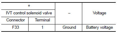
1.CHECK INTAKE VALVE TIMING CONTROL SOLENOID VALVE POWER SUPPLY
- Turn ignition switch OFF.
- Disconnect intake valve timing (IVT) control solenoid valve harness connector.
- Turn ignition switch ON.
- Check the voltage between intake valve timing control solenoid valve harness connector and ground.
Is the inspection result normal? YES >> GO TO 3.
NO >> GO TO 2.
2.CHECK INTAKE VALVE TIMING CONTROL SOLENOID VALVE POWER SUPPLY CIRCUIT
- Turn ignition switch OFF.
- Disconnect IPDM E/R harness connector.
- Check the continuity between IVT control solenoid valve harness connector and IPDM E/R harness connector.
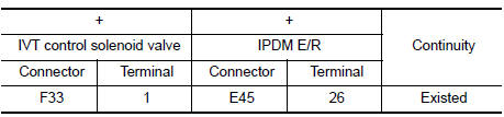
- Also check harness for short to ground.
Is the inspection result normal? YES >> Perform the trouble diagnosis for power supply circuit.
NO >> Repair or replace error-detected parts.
3.CHECK INTAKE VALVE TIMING CONTROL SOLENOID VALVE GROUND CIRCUIT
- Turn ignition switch OFF.
- Disconnect ECM harness connector.
- Check the continuity between IVT control solenoid valve harness connector and ECM harness connector.
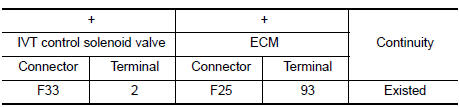
- Also check harness for short to ground and to power.
Is the inspection result normal? YES >> GO TO 4.
NO >> Repair or replace error-detected parts.
4.CHECK INTAKE VALVE TIMING CONTROL SOLENOID VALVE
Check the intake valve timing control solenoid valve. Refer to EC-181, "Component Inspection (IVT Control Solenoid Valve)".
Is the inspection result normal? YES >> Check intermittent incident. Refer to GI-39, "Intermittent Incident".
NO >> Replace intake valve timing control solenoid valve. Refer to EM-48, "Exploded View".
Component Inspection (IVT Control Solenoid Valve)
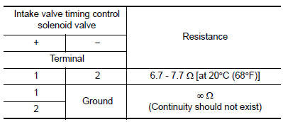
1.CHECK INTAKE VALVE TIMING CONTROL SOLENOID VALVE-1
- Turn ignition switch OFF.
- Disconnect intake valve timing control solenoid valve harness connector.
- Check resistance between intake valve timing control solenoid valve terminals as per the following.
Is the inspection result normal? YES >> GO TO 2.
NO >> Replace intake valve timing control solenoid valve. Refer to EM-48, "Exploded View".
2.CHECK INTAKE VALVE TIMING CONTROL SOLENOID VALVE-2
- Remove intake valve timing control solenoid valve. Refer to EM-48, "Exploded View".
- Provide 12 V DC between intake valve timing control solenoid valve terminals 1 and 2, and then interrupt it. Make sure that the plunger moves as shown in the figure.
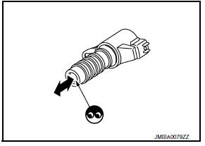
CAUTION:
Do not apply 12 V DC continuously for 5 seconds or more.
Doing so may result in damage to the coil in intake valve timing control solenoid valve.
NOTE:
Always replace O-ring when intake valve timing control solenoid valve is removed.
Is the inspection result normal? YES >> INSPECTION END
NO >> Replace intake valve timing control solenoid valve. Refer to EM-48, "Exploded View".
 P0037, P0038 HO2S2 Heater
DTC Logic
DTC DETECTION LOGIC
DTC No.
CONSULT screen terms
(Trouble diagnosis content)
DTC detecting condition
Possible cause
P0037
HO2 HTR (B1)
(HO2S heater contro ...
 P0078 EVT Control solenoid valve
DTC Logic
DTC DETECTION LOGIC
DTC No.
CONSULT screen terms
(Trouble diagnosis content)
DTC detecting condition
Possible cause
P0078
EX V/T ACT/CIRC-B1
(Exhaust valv ...
Other materials:
Engine oil
Inspection
Engine oil level
Note:
Before starting engine, put vehicle horizontally and check the engine oil
level. If engine is already started, stop
it and allow 10 minutes before checking.
Pull out oil level gauge and wipe it clean.
Insert oil level gauge and check that the engine oil ...
P050A, P050B, P050E Cold start control
Description
ECM controls ignition timing and engine idle speed when engine is started
with pre-warming up condition.
This control promotes the activation of three way catalyst by heating the
catalyst and reduces emissions.
DTC Logic
DTC DETECTION LOGIC
NOTE:
If DTC P050A, P050B or P050E ...
P0507 ISC System
Description
The ECM controls the engine idle speed to a specified level through the fine
adjustment of the air, which is let
into the intake manifold, by operating the electric throttle control actuator.
The operating of the throttle valve is
varied to allow for optimum control of the engine ...
