Nissan Sentra Service Manual: Headlamp (hi) circuit
Description
The IPDM E/R (intelligent power distribution module engine room) controls the headlamp high relay based on inputs from the BCM over the CAN communication lines. When the headlamp high relay is energized, power flows through fuses 41 and 42, located in the IPDM E/R. Power then flows to the front combination lamps to the headlamp high beam.
Component Function Check
1.CHECK HEADLAMP (HI) OPERATION
 WITHOUT CONSULT
- Start IPDM E/R auto active test. Refer to EXL-24, "Diagnosis Description" (with Intelligent Key system) or EXL-28, "Diagnosis Description" (without Intelligent Key system).
- Check that the headlamp switches to the high beam.
NOTE:
HI/LO is repeated 1 second each when using the IPDM E/R auto active test.
 CONSULT
- Select EXTERNAL LAMP of IPDM E/R active test item.
- While operating the test items, check that the headlamp switches to the high beam.
HI : Headlamp switches to the high beam.
OFF : Headlamp OFF
Is the inspection result normal? YES >> Headlamp (HI) circuit is normal.
NO >> Refer to EXL-88, "Diagnosis Procedure".
Diagnosis Procedure
Regarding Wiring Diagram information, refer to EXL-33, "Wiring Diagram".
1.Check headlamp (HI) Fuses
- Turn the ignition switch OFF.
- Check that the following fuses are not blown.
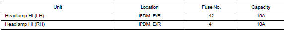
Is the fuse blown? YES >> Replace the fuse after repairing the affected circuit.
NO >> GO TO 2.
2.Check headlamp (HI) output voltage
 Consult active test
- Turn the ignition switch off.
- Disconnect the front combination lamp harness connector in question.
- Turn the ignition switch on.
- Select external lamp of ipdm e/r active test item.
- With external lamp on, check the voltage between the combination lamp connector and ground.
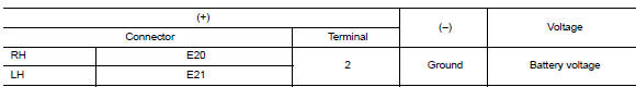
Is the inspection result normal? Yes >> go to 4.
No >> go to 3.
3.Check headlamp (hi) circuit for open
- Turn the ignition switch off.
- Disconnect ipdm e/r connector
- Check continuity between the IPDM E/R harness connector and the front combination lamp harness connector.
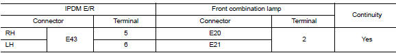
Is the inspection result normal? Yes >> replace ipdm e/r. Refer to pcs-30, "removal and installation" (with intelligent key system) or pcs-58, "removal and installation" (without intelligent key system).
No >> repair or replace the harness or connector.
4.Check front combination lamp (hi) ground circuit
Check continuity between the front combination lamp harness connector terminal and ground.
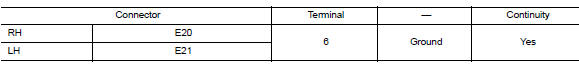
Is the inspection result normal? YES >> Inspect the headlamp bulb.
NO >> Repair or replace the harness or connector.

 Headlamp (lo) circuit
Description
The ipdm e/r (intelligent power distribution module engine room) controls the
headlamp low relay based on
inputs from the bcm over the can communication lines. When the headlamp low
...
Other materials:
Clutch disc and clutch cover
Exploded View
Flywheel
Clutch disc
Clutch cover
Input shaft
First step
Final step
Apply lithium-based grease
including molybdenum disulphide.
Removal and Installation
CAUTION:
Do not reuse CSC (Concentric Slave Cylinder). The CSC slides back
to the original posit ...
General Precautions
Do not operate the
engine for an extended period of time without proper exhaust ventilation.
Keep the work area well ventilated and free of any inflammable
materials. Special care should be taken when handling any inflammable
or poisonous materials, such as gasoline, refrigerant gas,
etc. Wh ...
iPod®* player operation with Navigation System (if so equipped)
Connecting iPod®
WARNINGDo not connect, disconnect or operate the
USB device while driving. Doing so can be
a distraction. If distracted you could lose
control of your vehicle and cause an accident
or serious injury.
CAUTION
Do not force the USB device into the
U ...
