Nissan Sentra Service Manual: Oil seal
Valve oil seal : Removal and Installation
REMOVAL
- Rotate crankshaft, and set piston whose valve oil seal is to be removed to TDC. This will prevent valve from dropping into cylinder.
CAUTION:
When rotating crankshaft, be careful to avoid scarring front cover with timing chain.
- Remove camshafts. Refer to EM-60, "Exploded View".
- Remove valve lifters. Refer to EM-60, "Exploded View".
- Remove valve collet, valve spring retainer, and valve spring using Tools
Tool number (A) : KV1016200 (J-26336-A)
Tool number (B) : KV10109220 ( — )
Tool number (C) : KV10115900 (J-26336-20)
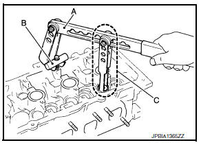
CAUTION:
- Do not damage valve lifter holes.
- Install Tool (A) in the center of valve spring retainer to press it.
(1) : Valve spring retainer
(A) : Attachment
Tool number : KV10115900 (J-26336-20)
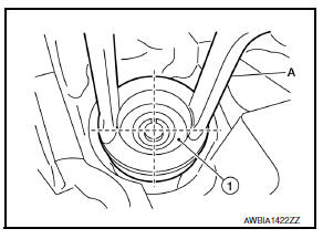
- Remove valve spring retainer and valve spring (with valve spring seat).
CAUTION:
Do not remove valve spring seat from valve spring.
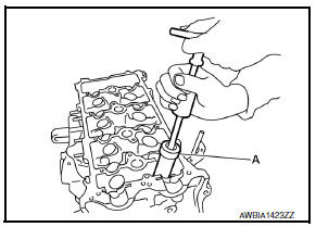
- Remove valve oil seal using Tool (A).
Tool number : KV10107902 (J-38959)
INSTALLATION
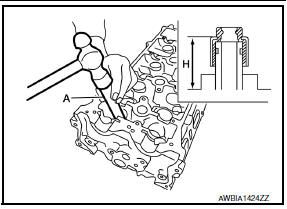
- Apply new engine oil to valve oil seal joint surface and seal lip.
- Press in valve oil seal to the height (H) shown using Tool (A).
Height (H) : 15.1 - 15.7 mm (0.594 - 0.618 in)
Tool number : KV10115600 (J-38958)
- Installation of remaining components is in the reverse order of removal.
Front oil seal : Removal and Installation
REMOVAL
- Remove front fender protector (RH). Refer to EXT-27, "FENDER PROTECTOR : Exploded View".
- Remove drive belt. Refer to EM-15, "Exploded View".
- Remove crankshaft pulley. Refer to EM-48, "Exploded View".
- Remove front oil seal using suitable tool.
CAUTION:
Do not damage front cover and crankshaft.
INSTALLATION
- Apply new engine oil to new front oil seal joint surface and seal lip.
- Install front oil seal so that each seal lip is oriented as shown.
(A) : Dust seal lip
(B) : Oil seal lip
- Press-fit front oil seal using a suitable tool with outer diameter 57 mm (2.24 in) and inner diameter 45 mm (1.77 in).
Within 0.3 mm (0.012 in) toward engine front (crankshaft pulley side)
Within 0.5 mm (0.020 in) toward engine rear (crankshaft sprocket side)
CAUTION:
- Be careful not to damage front cover and crankshaft.
- Press-fit oil seal straight to avoid causing burrs or tilting.
- Installation of remaining components is in the reverse order of removal.
Rear oil seal : Removal and Installation
REMOVAL
- Remove engine and transaxle assembly. Refer to EM-86, "CVT : Exploded View" (CVT models) or TM-28, "Exploded View" (M/T models).
- Remove clutch cover and clutch disc (M/T models). Refer to CL-17, "Exploded View".
- Remove drive plate (CVT models) or flywheel (M/T models). Refer to EM-94, "Exploded View".
- Remove rear oil seal using suitable tool.
CAUTION:
Do not damage crankshaft and cylinder block.
INSTALLATION
- Apply the liquid gasket lightly to entire outside area of new rear oil
seal.
Use Genuine Silicone RTV Sealant, or equivalent. Refer to GI-21, "Recommended Chemical Products and Sealants".
- Install rear oil seal so that each seal lip is oriented as shown.
(A) : Dust seal lip
(B) : Oil seal lip
- Press-fit rear oil seal using suitable tool (A) with outer diameter 115 mm (4.53 in) and inner diameter 90 mm (3.54 in).
CAUTION:
- Do not damage crankshaft and cylinder block.
- Press-fit oil seal straight to avoid causing burrs or tilting.
- Do not touch grease applied onto oil seal lip.
- Press in rear oil seal (1) to the position as shown.
(A) : Rear end surface of cylinder block
- Installation of the remaining components is in the reverse order of removal
 Camshaft
Exploded View
Camshaft position sensor (EXH)
O-ring
Camshaft bracket
Camshaft (EXH)
Camshaft sprocket (EXH)
Camshaft sprocket (INT)
Camshaft (INT)
Valve lifter (EXH)
Valve lif ...
 Cylinder head
Exploded View
Cylinder head assembly
Cylinder head bolt
Cylinder head gasket
Refer to INSTALLATION
Removal and Installation
REMOVAL
Release fuel pressure. Refer to EC-143, ...
Other materials:
Battery saver output/power supply circuit
Description
Provides the battery saver output/power supply. Also cuts the power supply
when the interior lamp battery
saver is activated.
Component function check
1.Check battery saver output/power supply function
Consult
Turn ignition switch on.
Turn each interior lamp to the ON posit ...
Evap leak check
Inspection
CAUTION:
Do not use compressed air or a high pressure pump.
Do not exceed 4.12 kPa (0.042 kg/cm2, 0.6 psi) of pressure in EVAP
system.
NOTE:
Do not start engine.
Improper installation of EVAP service port adapter [commercial
service tool: (J-41413-OBD)] to the EVAP
...
Precaution
Precaution for supplemental restraint system (srs) "air bag" and "seat belt
pre-tensioner"
The Supplemental Restraint System such as –≤–Ç—öAIR BAG–≤–Ç—ú and –≤–Ç—öSEAT BELT PRE-TENSIONER–≤–Ç—ú,
used along
with a front seat belt, helps to reduce the risk or severity of injur ...
