Nissan Sentra B18 (2020-2025) Service Manual: Oil Pan (upper)
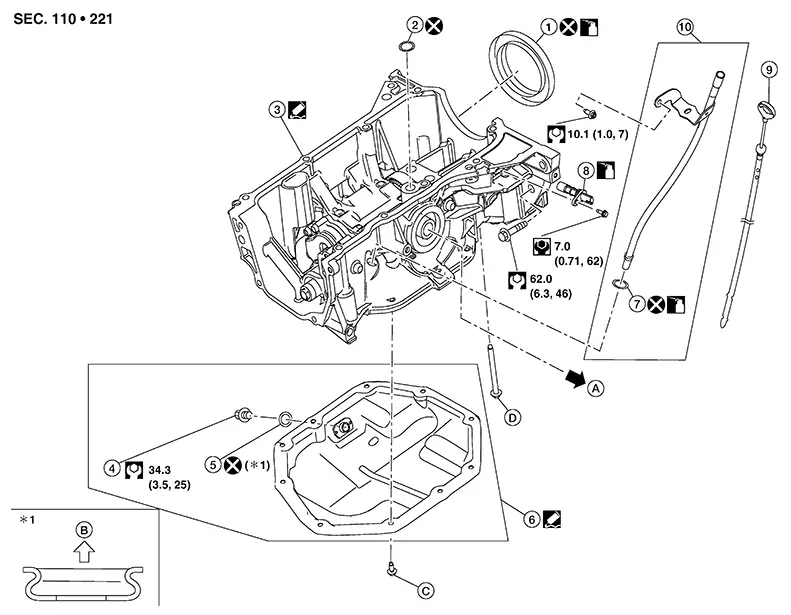
Exploded View
Exploded View
|
1. |
Rear oil seal |
2. |
O-ring |
3. |
Oil pan (upper) |
|
4. |
Drain plug |
5. |
Drain plug washer |
6. |
Oil pan (lower) |
|
7. |
O-ring |
8. |
Crankshaft position sensor (POS) |
9. |
Oil level gauge |
|
10. |
Oil level gauge guide |
A. |
To oil cooler. Refer to Exploded View. |
B. |
Oil pan (lower) side |
|
C. |
Refer to Removal and Installation. |
D. |
Refer to Removal and Installation. |
Removal and Installation
Removal and Installation
REMOVAL
CAUTION:
Oil pan (upper) is integral with oil pump balancer unit. Do not disassemble them.
Note:
When removing components such as hoses, tubes/lines, etc., cap or plug openings to prevent fluid from spilling.
Remove front cover, timing chain, balancer unit timing chain, and other related parts. Refer to Removal and Installation.
Remove oil
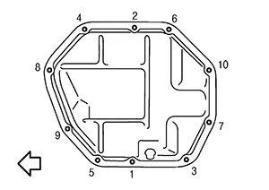
pan (lower) using the following procedure: Loosen oil pan (lower) bolts in
reverse of the sequence shown.
|
|
: Engine front |
CAUTION:
-
Be careful not to damage the mating surface.
-
Since factory default liquid gasket has better adhesion than conventional one, do not pick the area forcibly with a screw driver.
|
Tool number |
: KV10111100 (NI-37228) |
Remove the oil filter. Refer to Exploded View.
Remove the connector bolt and reposition the oil cooler. Refer to Exploded View.
Remove the exhaust manifold stay. Refer to Exploded View.
Remove the support bearing bracket. Refer to Exploded View.
Disconnect the harness connector from the crankshaft position sensor (POS).
Remove the crankshaft position sensor (POS).
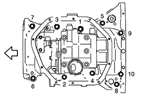
Remove oil
pan (upper) using the following procedure: Loosen oil pan (upper) bolts in
reverse of the sequence shown.
|
|
: Engine front |
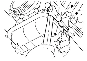
 )
and open up a crack between oil pan (upper) and cylinder
block.
)
and open up a crack between oil pan (upper) and cylinder
block.
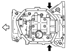
CAUTION:
-
Do not damage the mating surface.
-
The liquid gasket used at the factory is very strong. Pry only in the areas shown.
|
|
: Engine front |
CAUTION:
Be careful not to damage the mating surface.
|
Tool number |
: KV10111100 (NI-37228) |
Remove O-ring between cylinder block and oil pan (upper).
CAUTION:
Do not reuse O-ring.
Remove rear oil seal. Refer to Removal and Installation.
Remove torque rod stay from oil pan (upper) (if necessary). Refer to Exploded View.
INSTALLATION
Install oil
pan (upper) using the following procedure: Use a
suitable tool (A) to remove old liquid gasket from mating
surfaces.
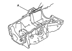
-
Remove the old liquid gasket from mating surface of cylinder block.
-
Remove old liquid gasket from the bolt holes and threads.
CAUTION:
Do not scratch or damage the mating surfaces when cleaning off old liquid gasket.
Apply a continuous bead of liquid gasket (C) with a suitable tool as shown.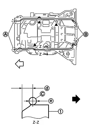
|
(1) |
: Oil pan (upper) |
|
(A) |
: 2 mm (0.08 in) protruded to outside |
|
(B) |
: 2 mm (0.08 in) protruded to rear oil seal mounting side |
|
(d) |
: 5.5 - 7.5 mm (0.217 - 0.295 in) |
|
(e) |
: 4.0 - 5.0 (0.157 - 0.197 in) |
|
|
: Engine front |
|
|
: Engine outside |
Use Genuine Silicone RTV Sealant or equivalent. Refer to Recommended Chemical Products and Sealants.
CAUTION:
-
Apply liquid gasket to outside of bolt hole for the positions shown by
 marks.
 -
Attaching should be done within 5 minutes after liquid gasket application.
-
Do not confirm torque after the 5 minutes have elapsed.
-
Then allow 30 minutes for the liquid gasket to set before adding oil to the engine.
CAUTION:
-
Install avoiding misalignment of O-ring.
-
Do not reuse O-ring.
CAUTION:
Remove any liquid gasket that protrudes onto the front cover or rear oil seal sealing surface.
|
Oil pan (upper) bolts |
: 25.5 N·m (2.6 kg-m, 19 ft-lb) |
|
|
: Engine front |
Install rear oil seal with the following procedure.
CAUTION:
-
The installation of rear oil seal should be completed within 5 minutes after installing oil pan (upper).
-
Do not reuse rear oil seal.
-
Do not touch oil seal lip.
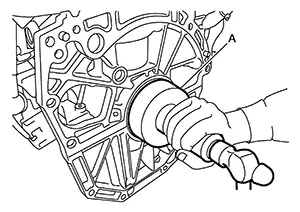
-
Press-fit the rear oil seal to the specified dimensions as shown.
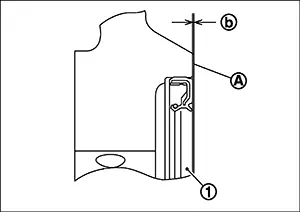
(1)
: Rear oil seal
(A)
: Rear end surface of cylinder block
(B)
: -0.3 - 0.5 mm (-0.012 - 0.020 in)
CAUTION:
-
Do not touch the grease applied to the oil seal lip.
-
Be careful not to damage the rear oil seal mounting part of oil pan (upper) and cylinder block or the crankshaft.
-
Press-fit straight, checking that rear oil seal does not curl or tilt.
The standard surface of the dimension is the rear end surface of cylinder block.
Install oil
pan (lower) using the following procedure: Use a
suitable tool (A) to remove old liquid gasket from mating
surfaces. 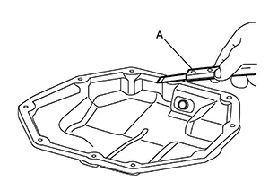
-
Also remove old liquid gasket from mating surface of oil pan (upper).
-
Remove old liquid gasket from the bolt holes and threads.
CAUTION:
Do not scratch or damage the mating surface when cleaning off old liquid gasket.
Apply a continuous bead of liquid gasket (C) with a suitable tool as shown.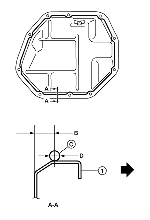
|
(1) |
: Oil pan (lower) |
|
(B) |
: 7.5 - 8.5 mm (0.295 - 0.374 in) |
|
(D) |
: 4.0 - 5.0 mm (0.157 - 0.197 in) |
|
|
: Engine outside |
Use Genuine Silicone RTV Sealant or equivalent. Refer to Recommended Chemical Products and Sealants.
CAUTION:
-
The components must be installed within 5 minutes of the liquid gasket application.
-
Do not confirm torque after 5 minutes have elapsed.
-
Then allow 30 minutes for the liquid gasket to set before adding oil to the engine.
|
Oil pan (lower) bolts |
: 10.1 N·m (1.0 kg-m, 7 ft-lb) |
Install drain plug.
CAUTION:
Do not reuse drain plug washer.
Installation of the remaining components is in the reverse order of removal.
Inspection
Inspection
INSPECTION AFTER REMOVAL
Clean oil strainer portion (part of the oil pump) if any object attached.
Other materials:
C1076-55 Control Unit
Dtc Description
DTC Description
DTC DETECTION LOGIC
DTC No.
CONSULT screen item
(Trouble diagnosis
content)
DTC detection condition
...
High Pressure Fuel Pump
Component Function Check
Component Function Check
CHECK HIGH PRESSURE FUEL PUMP
FUNCTION
With CONSULT
Start engine.
Select “FUEL PRES SEN V”
in “DATA MONITOR” mode of
“ENGINE” usi ...
Diagnosis System (bcm)
Common Item
Consult Function (bcm - Common Item)
CONSULT Function (BCM - COMMON ITEM)
BCM
Refer to CONSULT Function (BCM - COMMON ITEM).
Int Lamp
Consult Function (bcm - Int Lamp)
CON ...