Nissan Sentra B18 (2020-2025) Service Manual: High Pressure Fuel Pump
Component Function Check
Component Function Check
-
CHECK HIGH PRESSURE FUEL PUMP FUNCTION
 With CONSULT
-
Start engine.
-
Select ŌĆ£FUEL PRES SEN VŌĆØ in ŌĆ£DATA MONITORŌĆØ mode of ŌĆ£ENGINEŌĆØ using CONSULT and check the indication as per the following conditions.
Monitor item
Condition
Indication
FUEL PRES SEN V
At idle
0.820 ŌĆō 1,140 V
Revving engine up to 4,000 rpm quickly.
0.820 ŌĆō 2,900 V
 Without CONSULT
-
Start engine.
-
Check the voltage between ECM terminals as per the following conditions.
ECM
Condition
Voltage
Connector
+
ŌłÆ
Terminal
F25
67
68
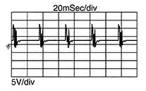
[Engine is running]
-
Warm-up condition
-
Idle speed
Note:
The pulse cycle changes depending on rpm at idle.
[Engine is running]
-
Warm-up condition
-
Engine speed: 2,000 rpm
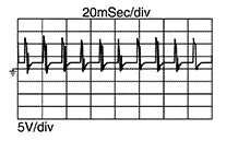
-
Is the inspection result normal?
YES >>INSPECTION END
NO >>Refer to Diagnosis Procedure.
-
Diagnosis Procedure
Diagnosis Procedure
-
CHECK FUSE
-
Turn ignition switch OFF.
-
Check that the following fuse is not blowing.
Fuse No.
Capacity
#68
10 A
Is the fuse blown (open)?
YES >>Replace the fuse after repairing the applicable circuit.
NO >>GO TO 2.
-
-
CHECK HIGH PRESSURE FUEL PUMP POWER SUPPLY
-
Turn ignition switch ON.
-
Check the voltage between ECM harness connector and ground.
+
ŌłÆ
Voltage
ECM
Connector
Terminal
F25
66
Ground
Battery voltage
Is the inspection result normal?
YES >>GO TO 9.
NO >>GO TO 3.
-
-
CHECK HIGH PRESSURE FUEL PUMP POWER SUPPLY CIRCUIT
-
Turn ignition switch OFF.
-
Disconnect ECM harness connector.
-
Disconnect high pressure fuel pump relay harness connector.
-
Check the continuity between ECM harness connector and high pressure fuel pump relay harness connector.
ECM
High pressure fuel pump relay
Continuity
Connector
Terminal
Connector
Terminal
F25
66
F61
2
Existed
-
Also check harness for short to ground and short to power.
Is the inspection result normal?
YES >>GO TO 4.
NO >>Repair or replace malfunctioning part.
-
-
CHECK HIGH PRESSURE FUEL PUMP RELAY POWER SUPPLY (CONTACT SIDE)
Check the voltage between high pressure fuel pump relay harness connector and ground.
+
ŌłÆ
Voltage
High pressure fuel pump relay
Connector
Terminal
F61
1
Ground
Battery voltage
Is the inspection result normal?
YES >>GO TO 5.
NO >>Perform the trouble diagnosis for power supply circuit.
-
CHECK HIGH PRESSURE FUEL PUMP RELAY POWER SUPPLY (EXCITATION COIL SIDE)
-
Install all removed parts.
-
Turn ignition switch ON.
-
Check the voltage between high pressure fuel pump relay harness connector and ground.
+
ŌłÆ
Voltage
High pressure fuel pump relay
Connector
Terminal
F61
3
Ground
Battery voltage
Is the inspection result normal?
YES >>GO TO 7.
NO >>GO TO 6.
-
-
CHECK HIGH PRESSURE FUEL PUMP RELAY POWER SUPPLY CIRCUIT (EXCITATION COIL SIDE)
-
Turn ignition switch OFF.
-
Disconnect IPDM E/R harness connector.
-
Disconnect high pressure fuel pump relay harness connector.
-
Check the continuity between IPDM E/R harness connector and high pressure fuel pump relay harness connector.
IPDM E/R
High pressure fuel pump relay
Continuity
Connector
Terminal
Connector
Terminal
F96
73
F61
3
Existed
-
Also check harness for short to ground and short to power.
Is the inspection result normal?
YES >>Perform the trouble diagnosis for power supply circuit.
NO >>Repair or replace malfunctioning part.
-
-
CHECK HIGH PRESSURE FUEL PUMP RELAY GROUND CIRCUIT
-
Turn ignition switch OFF.
-
Disconnect high pressure fuel pump relay harness connector.
-
Check the continuity between high pressure fuel pump relay harness connector and ground.
High pressure fuel pump relay
ŌĆö
Continuity
Connector
Terminal
F61
4
Ground
Existed
-
Also check harness for short to ground.
Is the inspection result normal?
YES >>GO TO 8.
NO >>Repair or replace malfunctioning part.
-
-
CHECK HIGH PRESSURE FUEL PUMP RELAY
Refer to Component Inspection.
Is the inspection result normal?
YES >>Check intermittent incident. Refer to Intermittent Incident.
NO >>Replace high pressure fuel pump relay.
-
CHECK ECM GROUND CIRCUIT
-
Turn ignition switch OFF.
-
Disconnect ECM harness connector.
-
Check the continuity between ECM harness connector and ground.
ECM
ŌĆö
Continuity
Connector
Terminal
F24
5
Ground
Existed
65
F25
69
E16
157
159
162
-
Also check harness for short to power.
Is the inspection result normal?
YES >>GO TO 10.
NO >>Repair or replace malfunctioning part.
-
-
CHECK HIGH PRESSURE FUEL PUMP CIRCUIT
-
Disconnect high pressure fuel pump relay harness connector.
-
Check the continuity between ECM harness connector and high pressure fuel pump harness connector.
ECM
High pressure fuel pump
Continuity
Connector
Terminal
Connector
Terminal
F25
67
F32
1
Existed
68
2
-
Also check harness for short to ground and short to power.
Is the inspection result normal?
YES >>GO TO 11.
NO >>Repair or replace malfunctioning part.
-
-
CHECK HIGH PRESSURE FUEL PUMP
Refer to Component Inspection.
Is the inspection result normal?
YES >>GO TO 12.
NO >>Replace high pressure fuel pump. Refer to Removal and Installation.
-
CHECK HIGH PRESSURE FUEL PUMP INSTALLATION
-
Turn ignition switch OFF.
-
Check high pressure fuel pump for improper attachment or looseness.
Is the inspection result normal?
YES >>GO TO 13.
NO >>Repair or replace malfunctioning part.
-
-
CHECK CAMSHAFT
-
Remove camshaft. Refer to Removal and Installation.
-
Check camshaft. Refer to Inspection.
Is the inspection result normal?
YES >>Check intermittent incident. Refer to Intermittent Incident.
NO >>Replace camshaft. Refer to Removal and Installation.
-
Component Inspection
Component Inspection
-
CHECK HIGH PRESSURE FUEL PUMP-1
-
Turn ignition switch OFF.
-
Disconnect high pressure fuel pump harness connector.
-
Check the resistance between high pressure fuel pump terminals as per the following conditions.
High pressure fuel pump
Condition
Resistance
Terminal
1
2
Temperature [┬░C (┬░F)]
20 ŌĆō 30 (68 ŌĆō 86)
0.46 ŌĆō 0.51 Ōä”
Is the inspection result normal?
YES >>GO TO 2.
NO >>Replace high pressure fuel pump. Refer to Exploded View.
-
-
CHECK HIGH PRESSURE FUEL PUMP-2
With CONSULT-
Reconnect high pressure fuel pump harness connector.
-
Start engine.
-
Select ŌĆ£FUEL PRES SEN VŌĆØ in ŌĆ£DATA MONITORŌĆØ mode of ŌĆ£ENGINEŌĆØ using CONSULT and check the indication as per the following conditions.
Monitor item
Condition
Indication
FUEL PRES SEN V
At idle
0.820 ŌĆō 1.140 V
Revving engine up to 4,000 rpm quickly.
0.820 ŌĆō 2.900 V
Without CONSULT-
Start engine.
-
Check fuel rail pressure sensor signal voltage.
ECM
Condition
Voltage
(Approx.)
Connector
+
ŌłÆ
Terminal
F24
44
45
[Engine is running]
-
Warm-up condition
-
Idle speed
0.82 ŌĆō 1.14 V
[Engine is running]
-
Warm-up condition
-
Engine speed: Revving engine from idle to 4,000 rpm
0.82 ŌĆō 2.90 V
Is the inspection result normal?
YES >>INSPECTION END
NO >>Replace high pressure fuel pump. Refer to Exploded View.
-
Other materials:
Bluetooth connections screen
"
"
(back) key
Bluetooth tab
Connections screen
"Add New" key
"
"
(settings) key
"
"
(info) key
"
"
(Bluetooth Audio connection) key
"
"
(Bluetooth Hands-Free Phone
System connection) key
U ...
P052a Intake Valve Timing Control
Dtc Description
DTC Description
DTC DETECTION LOGIC
DTC No.
CONSULT screen terms
(Trouble diagnosis
content)
DTC detecting
condition
...
P0014 Evt Control
Dtc Description
DTC Description
DTC DETECTION LOGIC
DTC
CONSULT screen terms
(Trouble diagnosis
content)
DTC detection
condition
...