Nissan Sentra B18 (2020-2025) Service Manual: Magnet Clutch
Removal and Installation
REMOVAL
Remove front wheel and tire (RH). Refer to Removal and Installation.
Partially remove the front fender protector (RH). Refer to Exploded View.
Remove the front under cover. Refer to Removal and Installation.
Remove the
drive belt from the compressor. Refer to Removal and Installation. Note: 
Complete removal of the drive belt is not necessary.
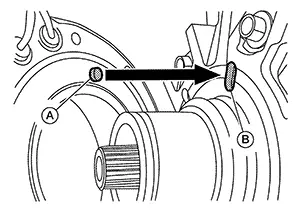
Hold clutch
disc (1) using tool (A) then remove center bolt (B). 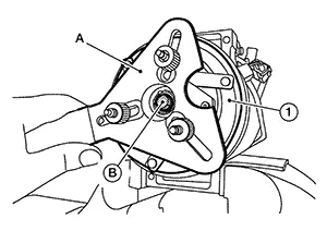
Remove the clutch disc and shim(s).
CAUTION:
Retain shim(s) for installation.
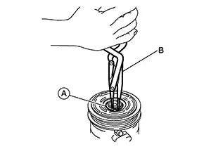
Remove the
snap ring (A) using a suitable tool (B).
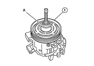
Remove the
pulley assembly using suitable tool (A).
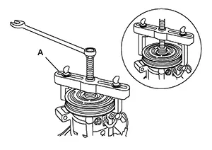
CAUTION:
To prevent deformation of the pulley groove, the puller claws should be hooked under (not into) the pulley groove.
Remove the
magnet coil snap ring (A) using a suitable tool.
Then remove the magnet coil (1) from compressor shaft.
INSPECTION AFTER REMOVAL
Clutch Disc
If the contact surface shows signs of damage due to excessive heat, replace clutch disc and pulley.
Pulley
Check the appearance of the pulley assembly. If the contact surface of the pulley shows signs of excessive grooving, replace the clutch disc and pulley. The contact surfaces of the pulley assembly should be cleaned with a suitable solvent before installation.
Magnet Coil
Check the magnet coil for a loose connection or cracked insulation.
INSTALLATION
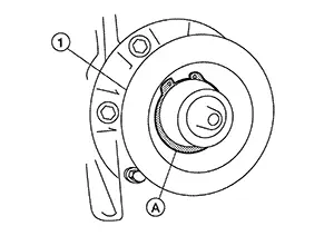
Install the magnet coil.
CAUTION:
Be sure to align the magnet coil pin (A) with the hole (B) in the compressor front head.
Install the
magnet coil (1) on the compressor shaft with the snap ring (A)
using suitable tool.
Install the
pulley assembly (1) using Tool (A).
|
Tool number |
: — (NI-38873-A) |
Install the
snap ring (A) using a suitable tool (B).
Hold clutch
disc using tool (A) then tighten center bolt.
Installation of remaining components is in reverse order of removal.
INSPECTION OF CLUTCH DISC TO PULLEY CLEARANCE
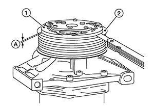
Check the
clearance (A) all the way around between the clutch disc (1) and
pulley (2).
|
Clutch disc to pulley clearance |
: 0.35 - 0.65 mm (0.014 - 0.026 in) |
If specified clearance is not obtained, replace compressor clutch.
BREAK-IN OPERATION
When replacing compressor clutch assembly, always conduct the break-in operation. This is done by engaging and disengaging the clutch about 30 times. Break-in operation raises the level of transmitted torque.
 Removal and Installation
Removal and Installation
REMOVAL
Discharge
the refrigerant. Refer to Recycle Refrigerant.
Partially
remove the front fender protector (RH). Refer to Exploded View.
Remove the
...

Other materials:
B2e05 Air Bag Can
Dtc Description
DTC Description
DTC DETECTION LOGIC
DTC No.
CONSULT screen terms
(Trouble diagnosis
content)
DTC detection condition
...
Intelligent Key Unit
Diagnosis Procedure
Diagnosis Procedure
CHECK FUSE
Check that the following fuse is not blown:
...
B2223-16 Combination Meter
Dtc Description
DTC Description
DTC DETECTION LOGIC
DTC No.
CONSULT screen terms
(Trouble diagnosis
content)
DTC detected condition
...
