Nissan Sentra B18 (2020-2025) Service Manual: Low Pressure Fuel Pump
Component Function Check
Component Function Check
-
CHECK LOW PRESSURE FUEL PUMP FUNCTION
-
Turn ignition switch ON.
-
Pinch fuel feed hose
 with two fingers.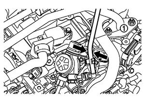
Fuel pressure pulsation should be felt on the fuel feed hose for 1 second after ignition switch is turned ON.
Is the inspection result normal?
YES >>INSPECTION END
NO >>Refer to Diagnosis Procedure.
-
Diagnosis Procedure
Diagnosis Procedure
-
CHECK FUEL PUMP RELAY POWER SUPPLY
-
Turn ignition switch OFF.
-
Disconnect ECM harness connector.
-
Turn ignition switch ON.
-
Check the voltage between ECM harness connector terminals.
ECM
Voltage
Connector
Terminal
Connector
Terminal
F25
118
E16
162
Battery voltage
Is the inspection result normal?
YES >>GO TO 3.
NO >>GO TO 2.
-
-
CHECK FUEL PUMP RELAY POWER SUPPLY CIRCUIT
-
Turn ignition switch OFF.
-
Disconnect IPDM E/R harness connector.
-
Check the continuity between ECM harness connector and IPDM E/R harness connector.
ECM
IPDM E/R
Continuity
Connector
Terminal
Connector
Terminal
F25
118
F96
76
Existed
-
Also check harness for short to power.
Is the inspection result normal?
YES >>Perform trouble diagnosis for power supply circuit.
NO >>Repair or replace malfunctioning part.
-
-
CHECK FUEL PUMP POWER SUPPLY
-
Turn ignition switch OFF.
-
Reconnect ECM harness connector.
-
Disconnect “fuel level sensor unit and fuel pump� harness connector.
-
Turn ignition switch ON.
-
Check the voltage between “fuel level sensor unit and fuel pump� harness connector and ground.
+
−
Voltage
Fuel level sensor unit and fuel pump
Connector
Terminal
B48
8
Ground
Battery voltage should exist 1 second after ignition switch is turn ON.
Is the inspection result normal?
YES >>GO TO 5.
NO >>GO TO 4.
-
-
CHECK FUEL PUMP POWER SUPPLY CIRCUIT
-
Turn ignition switch OFF.
-
Disconnect IPDM E/R harness connector.
-
Check the continuity between “fuel level sensor unit and fuel pump� harness connector and IPDM E/R harness connector.
Fuel level sensor unit and fuel pump
IPDM E/R
Continuity
Connector
Terminal
Connector
Terminal
B48
8
E45
46
Existed
-
Also check harness for short to power.
Is the inspection result normal?
YES >>Perform trouble diagnosis for power supply circuit.
NO >>Repair or replace malfunctioning part.
-
-
CHECK FUEL PUMP GROUND CIRCUIT
-
Turn ignition switch OFF.
-
Check the continuity between “fuel level sensor unit and fuel pump� harness connector and ground.
Fuel level sensor unit and fuel pump
—
Continuity
Connector
Terminal
B48
7
Ground
Existed
-
Also check harness for short to ground and to power.
Is the inspection result normal?
YES >>GO TO 6.
NO >>Repair or replace malfunctioning part.
-
-
CHECK FUEL PUMP
Check fuel pump. Refer to Component Inspection.
Is the inspection result normal?
YES >>Check intermittent incident. Refer to Intermittent Incident.
NO >>Replace “fuel level sensor unit and fuel pump�. Refer to Removal and Installation.
Other materials:
C161a-83 Abs System
Dtc Description
DTC Description
DTC DETECTION LOGIC
DTC No.
CONSULT screen terms
(Trouble diagnosis content)
DTC detection condition
...
Unit Disassembly and Assembly
Rear Combination Lamp (body Side)
Exploded View
Exploded View
1.
Rear combination lamp
2.
Stop/tail lamp bulb
...
Preparation. Preparation
Preparation
Special Service Tool
Special Service Tool
The actual shape of the tools may differ from those
illustrated here.
Tool number
(TechMate No.)
Tool name
...