Nissan Sentra Service Manual: L terminal circuit (short)
Description
The terminal “l” circuit controls the charge warning lamp. The charge warning lamp turns on when the ignition switch is set to on or start. When the generator is providing sufficient voltage with the engine running, the charge warning lamp turns off. If the charge warning lamp illuminates with the engine running, a malfunction is indicated.
Diagnosis Procedure
Regarding wiring diagram information, refer to chg-9, "wiring diagram".
1.Check “l” terminal circuit (short)
- Turn ignition switch off.
- Disconnect generator connector.
- Turn ignition switch on.
Does charge warning lamp illuminate? YES >> GO TO 2.
NO >> Refer to CHG-14, "Work Flow (With EXP-800 NI or GR8-1200 NI)" or CHG-17, "Work Flow (Without EXP-800 NI or GR8-1200 NI)".
2.Check harness continuity (short circuit)
- Turn ignition switch off.
- Disconnect the battery cable from the negative terminal.
- Disconnect combination meter connector.
- Check continuity between the combination meter harness connector and ground.
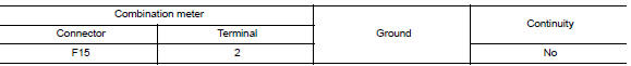
Is the inspection result normal? Yes >> replace the combination meter. Refer to mwi-77, "removal and installation".
No >> repair or replace the harness or connectors.
 L terminal circuit (open)
Description
The “L” terminal circuit controls the charge warning lamp. The charge warning
lamp turns ON when the ignition
switch is set to ON or START. When the generator is providing su ...
 S terminal circuit
Description
The output voltage of the generator is controlled by the IC regulator at
terminal “S” detecting the input voltage
from battery.
The “S” terminal circuit detects ...
Other materials:
Vents
Adjust air flow direction by moving the vent
slides.
Open or close the vents by using the dial. Move
the dial toward the to open the
vents or
toward the to close them.
...
Ecm branch line circuit
Diagnosis procedure
1.Check connector
Turn the ignition switch OFF.
Disconnect the battery cable from the negative terminal.
Check the terminals and connectors of the ECM for damage, bend and loose
connection (unit side and
connector side).
Is the inspection result normal?
Yes > ...
Measurement of weights
Secure loose items to prevent weight
shifts that could affect the balance of your
vehicle. When the vehicle is loaded, drive
to a scale and weigh the front and the rear
wheels separately to determine axle
loads. Individual axle loads should not exceed
either of the gross axle weight ratings
( ...
