Nissan Sentra Service Manual: S terminal circuit
Description
The output voltage of the generator is controlled by the IC regulator at terminal –≤–Ç—öS–≤–Ç—ú detecting the input voltage from battery.
The –≤–Ç—öS–≤–Ç—ú terminal circuit detects the battery voltage to adjust the generator output voltage with the IC voltage regulator.
Diagnosis procedure
Regarding wiring diagram information. Refer to chg-9, "wiring diagram".
1.Check –≤–Ç—ös–≤–Ç—ú terminal connection
- Turn ignition switch OFF.
- Check if –≤–Ç—ös–≤–Ç—ú terminal is clean and tight.
Is the inspection result normal? Yes >> go to 2.
No >> repair –≤–Ç—ös–≤–Ç—ú terminal connection. Confirm repair by performing complete charging system test using exp-800 ni or gr8-1200 ni (if available). Refer to the applicable instruction manual for proper testing procedures.
2.Check –≤–Ç—ös–≤–Ç—ú terminal circuit
Check voltage between generator harness connector and ground.
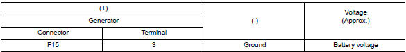
Is the inspection result normal? Yes >> refer to chg-14, "work flow (with exp-800 ni or gr8-1200 ni)" or chg-17, "work flow (without exp-800 ni or gr8-1200 ni)".
No >> check harness for open between generator and fuse.
 L terminal circuit (short)
Description
The terminal –≤–Ç—öl–≤–Ç—ú circuit controls the charge warning lamp. The charge warning
lamp turns on when the ignition
switch is set to on or start. When the generator is providing s ...
 Symptom diagnosis
Charging system
Symptom table
...
Other materials:
Cargo net (if so equipped)
WARNING
Properly secure all cargo with ropes or
straps to help prevent it from sliding or
shifting. In a sudden stop or collision,
unsecured cargo could cause personal
injury.
Be sure to secure all four hooks into the
retainers. The cargo restrained in the
net ...
NISSAN vehicle immobilizer system
The NISSAN Vehicle Immobilizer system will not
allow the engine to start without the use of the
registered key.
If the engine fails to start using a registered key
(for example, when interference is caused by
another registered key, an automated toll road
device or automatic payment device o ...
How to Check Terminal
CONNECTOR AND TERMINAL PIN KIT
Use the connector and terminal pin kits listed below when replacing
connectors or terminals.
The connector and terminal pin kits contain some of the most commonly
used NISSAN/INFINITI connectors
and terminals. For detailed connector and terminal pin repla ...
