Nissan Sentra Service Manual: System description
Component parts
Component parts location
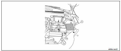
- Ipdm e/r
System
Relay control system
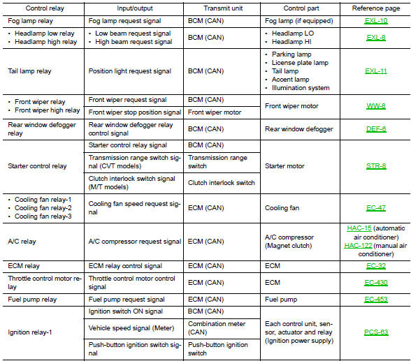
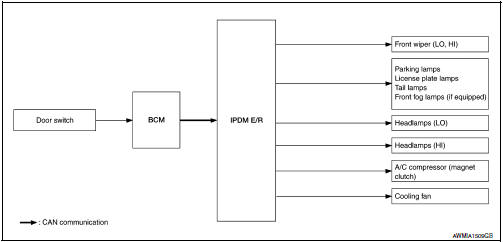
Relay control system : system diagram
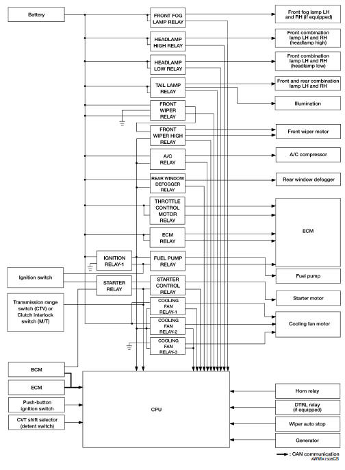
Relay control system : system description
Description
IPDM E/R activates the internal control circuit to perform the relay ON-OFF control according to the input signals from various sensors and the request signals received from control units via CAN communication.
Caution:
Ipdm e/r integrated relays cannot be removed.
Power consumption control system
Power consumption control system : system diagram
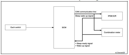
Power consumption control system : system description
Description
Outline
- Ipdm e/r incorporates a power consumption control function that reduces the power consumption according to the vehicle status.
- Ipdm e/r changes its status (control mode) with the sleep wake up signal received from bcm via can communication.
Normal mode (wake-up)
- Can communication is normally performed with other control units.
- Individual unit control by ipdm e/r is normally performed.
Low power consumption mode (sleep)
- Low power consumption control is active.
- CAN transmission is stopped.
Sleep mode activation
- Ipdm e/r judges that the sleep-ready conditions are fulfilled when the ignition switch is off and none of the conditions below are present. Then it transmits a sleep-ready signal (ready) to bcm via can communication.
- Outputting signals to actuators
- Switches or relays operating
- Output requests are being received from control units via CAN communication.
- Ipdm e/r stops can communication and enters the low power consumption mode when it receives a sleep wake up signal (sleep) from bcm and the sleep-ready conditions are fulfilled.
Wake-up operation
Ipdm e/r changes from the low power consumption mode to the normal mode when it receives a sleep wake-up signal (wake up) from bcm or any of the following conditions is fulfilled. In addition, it transmits a sleep-ready signal (not-ready) to bcm via can communication to report the can communication start.
- Ignition switch on
- An output request is received from a control unit via can communication.
Diagnosis system (ipdm e/r)
Diagnosis description
Auto active test
Description
In auto active test, the ipdm e/r sends a drive signal to the following systems to check their operation.
- Front wiper (lo, hi)
- Parking lamp
- License plate lamp
- Tail lamp
- Front fog lamp (if equipped)
- Headlamp (lo, hi)
- A/c compressor (magnet clutch)
- Cooling fan
Operation procedure
Note:
Never perform auto active test in the following conditions.
- Passenger door is open
- CONSULT is connected
- Close the hood and lift the wiper arms from the windshield. (Prevent windshield damage due to wiper operation)
Note:
When auto active test is performed with hood opened, sprinkle water on windshield beforehand.
- Turn the ignition switch off.
- Turn the ignition switch ON, and within 20 seconds, press the driver door switch 10 times. Then turn the ignition switch OFF
- Turn the ignition switch on within 10 seconds. After that the horn sounds once and the auto active test starts.
- After a series of the following operations is repeated 3 times, auto active test is completed.
Note:
- When auto active test has to be cancelled halfway through test, turn the ignition switch off.
- When auto active test is not activated, door switch may be the cause. Check door switch. Refer to DLK-103, "Component Inspection".
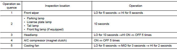
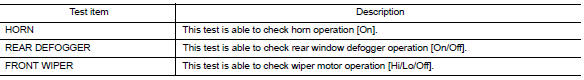
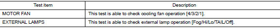
Inspection in auto active test
When auto active test is actuated, the following operation sequence is repeated 3 times.
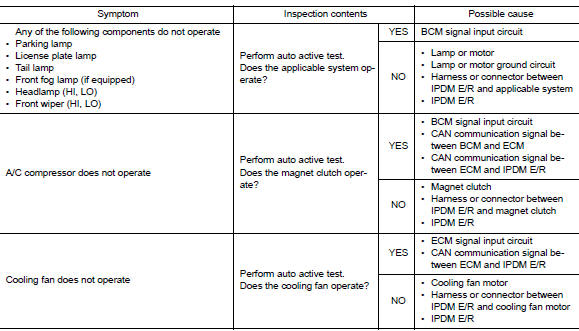
Concept of auto active test
- Ipdm e/r starts the auto active test with the door switch signals
transmitted by bcm via can communication.
Therefore, the can communication line between ipdm e/r and bcm is considered normal if the auto active test starts successfully.
- The auto active test facilitates troubleshooting if any systems controlled by IPDM E/R cannot be operated.
Diagnosis chart in auto active test
Consult function (ipdm e/r)
Application item
Consult performs the following functions via can communication with ipdm e/r.
| Direct diagnostic mode | Description |
| Ecu identification | The ipdm e/r part number is displayed. |
| Self diagnostic result | The IPDM E/R self diagnostic results are displayed. |
| Data Monitor | The ipdm e/r input/output data is displayed in real time. |
| Active Test | The ipdm e/r activates outputs to test components. |
| Can diag support mntr | The result of transmit/receive diagnosis of CAN communication is displayed. |
Ecu identification
The ipdm e/r part number is displayed.
Self diagnostic result
Refer to PCS-20, "DTC Index".
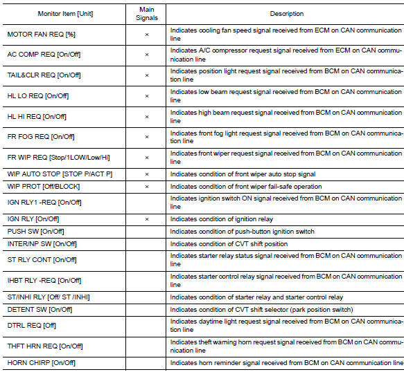
Data monitor
Active test
Can diag support mntr
Refer to lan-13, "can diagnostic support monitor".
 Precaution
Precaution for Supplemental Restraint System (SRS) "AIR BAG" and "SEAT BELT
PRE-TENSIONER"
The supplemental restraint system such as “air bag” and “seat belt pre- ...
 Ecu diagnosis information
Ipdm e/r (intelligent power distribution module engine room)
Reference Value
Values on the diagnosis tool
Terminal layout
Physical values
Fail-safe
Can communic ...
Other materials:
Battery saver output/power supply circuit
Description
Provides the battery saver output/power supply. Also cuts the power supply
when the interior lamp battery
saver is activated.
Component function check
1.Check battery saver output/power supply function
Consult
Turn ignition switch on.
Turn each interior lamp to the ON posit ...
Evap leak check
Inspection
CAUTION:
Do not use compressed air or a high pressure pump.
Do not exceed 4.12 kPa (0.042 kg/cm2, 0.6 psi) of pressure in EVAP
system.
NOTE:
Do not start engine.
Improper installation of EVAP service port adapter [commercial
service tool: (J-41413-OBD)] to the EVAP
...
License plate lamp
Removal and Installation
REMOVAL
Remove the license lamp finisher. Refer to EXT-44, "Removal and
Installation".
Disconnect the harness connector (A) from the license plate
lamp (1).
Release pawl and remove.
: Pawl
INSTALLATION
Installation is in the reverse order of ...
