Nissan Sentra Service Manual: L terminal circuit (open)
Description
The “L” terminal circuit controls the charge warning lamp. The charge warning lamp turns ON when the ignition switch is set to ON or START. When the generator is providing sufficient voltage with the engine running, the charge warning lamp turns OFF. If the charge warning lamp illuminates with the engine running, a malfunction is indicated.
Diagnosis procedure
Regarding Wiring Diagram information. Refer to CHG-9, "Wiring Diagram".Ð Ñš
1.Check “l” terminal connection
- Turn ignition switch off.
- Check if “l” terminal is clean and tight.
Is the inspection result normal? Yes >> go to 2.
No >> repair “l” terminal connection. Confirm repair by performing complete charging system test using exp-800 ni or gr8-1200 ni (if available). Refer to applicable instruction manual for proper testing procedures.
2.Check “l” terminal circuit (open)
- Disconnect the generator connector.
- Apply ground to generator harness connector terminal.
- Check condition of the charge warning lamp with the ignition switch in the on position.
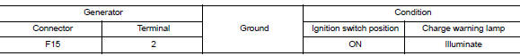
Does it illuminate? YES >> “L” terminal circuit is normal. Refer to CHG-14, "Work Flow (With EXP-800 NI or GR8-1200 NI)" or CHG-17, "Work Flow (Without EXP-800 NI or GR8-1200 NI)".
NO >> GO TO 3.
3.Check harness continuity (open circuit)
- Disconnect the battery cable from the negative terminal.
- Disconnect the combination meter connector.
- Check continuity between generator harness connector and combination meter harness connector.
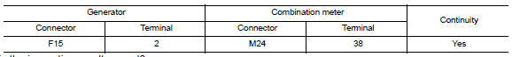
Is the inspection result normal? Yes >> go to 4.
No >> repair or replace the harness or connectors.
4.Check power supply circuit
- Connect the battery cable to the negative terminal.
- Check voltage between combination meter harness connector and ground.
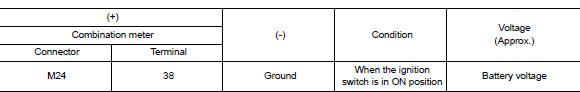
Is the inspection result normal? Yes >> replace the combination meter. Refer to mwi-77, "removal and installation".
No >> repair or replace the harness or connectors.
 B terminal circuit
Description
“B” terminal circuit supplies power to charge the battery and to operate the
vehicles electrical system.
Diagnosis procedure
Regarding wiring diagram information. Refer to c ...
 L terminal circuit (short)
Description
The terminal “l” circuit controls the charge warning lamp. The charge warning
lamp turns on when the ignition
switch is set to on or start. When the generator is providing s ...
Other materials:
M&A branch line circuit
Diagnosis procedure
1.Check connector
Turn the ignition switch off.
Disconnect the battery cable from the negative terminal.
Check the terminals and connectors of the combination meter for damage,
bend and loose connection
(unit side and connector side).
Is the inspection result nor ...
NISSAN Intelligent Key® (if so equipped)
WARNING
Radio waves could adversely affect
electric medical equipment. Those who
use a pacemaker should contact the
electric medical equipment manufacturer
for the possible influences before
use.
The Intelligent Key transmits radio
waves when the buttons are pr ...
Normal operating condition
Description
FUEL CUT CONTROL (AT NO LOAD AND HIGH ENGINE SPEED)
If the engine speed is above 2,500 rpm under no load (for example, the
selector lever position is neutral and
engine speed is over 2,500 rpm) fuel will be cut off after some time. The exact
time when the fuel is cut off varies
b ...
