Nissan Sentra Service Manual: M&A branch line circuit
Diagnosis procedure
1.Check connector
- Turn the ignition switch off.
- Disconnect the battery cable from the negative terminal.
- Check the terminals and connectors of the combination meter for damage, bend and loose connection (unit side and connector side).
Is the inspection result normal? Yes >> go to 2.
No >> repair the terminal and connector.
2.Check harness for open circuit
- Disconnect the connector of combination meter.
- Check the resistance between the combination meter harness connector terminals.
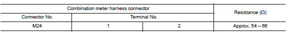
Is the measurement value within the specification? Yes >> go to 3.
No >> repair the combination meter branch line.
3.Check power supply and ground circuit
Check the power supply and the ground circuit of the combination meter. Refer to mwi-52, "combination meter : diagnosis procedure".
Is the inspection result normal? Yes (present error)>>replace the combination meter. Refer to mwi-77, "removal and installation".
Yes (past error)>>error was detected in the combination meter branch line.
No >> repair the power supply and the ground circuit.
 Eps branch line circuit
Diagnosis procedure
1.Check connector
Turn the ignition switch OFF.
Disconnect the battery cable from the negative terminal.
Check the terminals and connectors of the eps control unit for dam ...
 Strg branch line circuit
Diagnosis procedure
1.Check connector
Turn the ignition switch off.
Disconnect the battery cable from the negative terminal.
Check the terminals and connectors of the steering angle sensor fo ...
Other materials:
Precaution for Supplemental Restraint System (SRS) "AIR BAG" and "SEAT BELT
PRE-TENSIONER"
The Supplemental Restraint System such as “AIR BAG” and “SEAT BELT PRE-TENSIONER”,
used along
with a front seat belt, helps to reduce the risk or severity of injury to the
driver and front passenger for certain
types of collision. Information necessary to service the system ...
Checking engine oil level
Park the vehicle on a level surface and apply
the parking brake.
Start the engine and let it idle until it reaches
operating temperature.
Turn off the engine. Wait more than
10 minutes for the oil to drain back into
the oil pan.
Remove the dipstick and wipe it clean. Reinsert
...
High-mounted stop lamp
Removal and Installation
HIGH-MOUNTED STOP LAMP - WITH REAR SPOILER
Removal
Remove the rear air spoiler. Refer to EXT-46, "Removal and
Installation".
Remove the screws and the high-mount stop lamp from the rear air
spoiler.
Installation
Installation is in the reverse or ...
