Nissan Sentra B18 (2020-2025) Service Manual: How to Follow Trouble Diagnoses
Description
Description
Note:
Trouble diagnoses indicate work procedures required to diagnose problems effectively. Observe the following instructions before diagnosing.
-
Before performing trouble diagnoses, read the “Work Flow� in each section.
-
After repairs, re-check that the problem has been completely eliminated.
-
Refer to Component Parts and Harness Connector Location for the Systems described in each section for identification/location of components and harness connectors.
-
When checking circuit continuity, ignition switch should be OFF.
-
Refer to the Circuit Diagram for quick pinpoint check.
If you need to check circuit continuity between harness connectors in more detail, such as when a sub-harness is used, refer to Wiring Diagram in each individual section and Harness Layout in PG section for identification of harness connectors.
-
Before checking voltage at connectors, check battery voltage.
-
After accomplishing the Diagnosis Procedures and Electrical Components Inspection, make sure that all harness connectors are reconnected as they were.
How to Follow Test Groups in Trouble Diagnosis
How to Follow Test Groups in Trouble Diagnosis
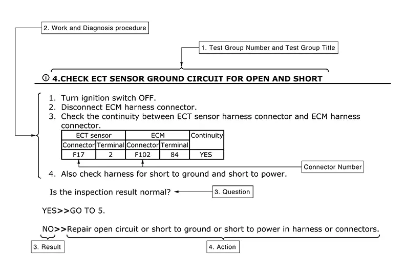
-
Test group number and test group title
-
Test group number and test group title are shown in the upper portion of each test group.
-
-
Work and diagnosis procedure
-
Start a trouble diagnosis using procedures indicated in enclosed test groups.
-
-
Questions and results
-
Questions and required results are indicated in test group.
-
-
Action
-
Next action for each test group is indicated based on result of each question.
-
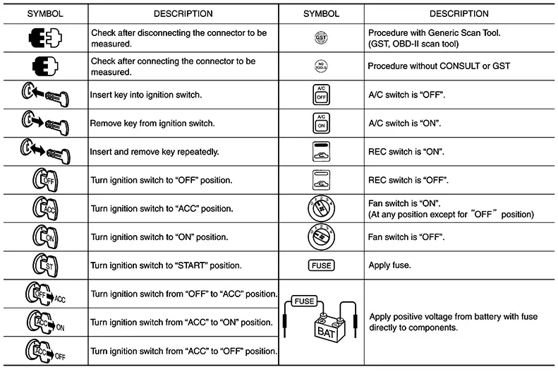
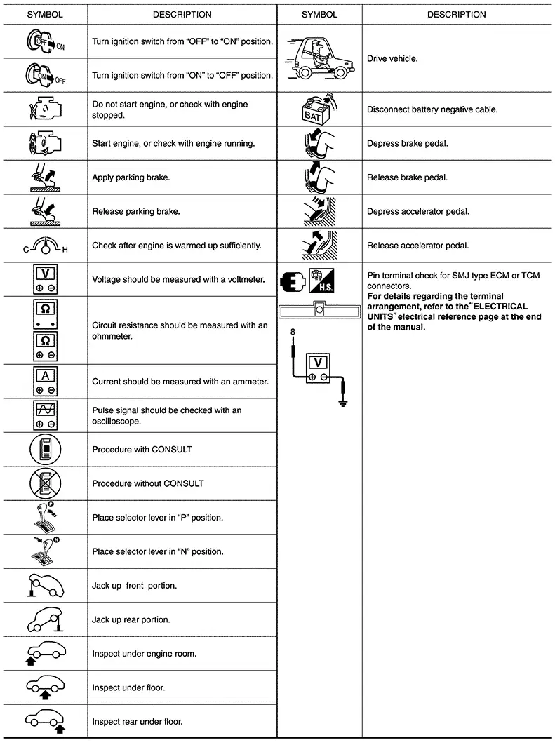
Key to Symbols Signifying Measurements or Procedures
Key to Symbols Signifying Measurements or Procedures
Other materials:
Steering System. Unit Removal and Installation. Steering Gear and Linkage
Steering Gear and Linkage
Exploded View
Exploded View
REMOVAL
1.
Steering gear and linkage
assembly
2.
Front su ...
Fuel Pump
Component Inspection
Component Inspection
CHECK FUEL PUMP
Turn ignition switch OFF.
Disconnect “fuel level sensor
unit and fuel pump� harness connector.
Check the resistance between
...
B24b0-14 Front Heated Seat Relay Lh (hi)
Dtc Description
DTC Description
DTC DETECTION LOGIC
DTC No.
CONSULT screen terms
(Trouble diagnosis name)
DTC detection condition
...