Nissan Sentra B18 (2020-2025) Service Manual: How to Use This Manual
Description
Description
This volume explains “Removal, Disassembly, Installation, Inspection and Adjustment� and “Trouble Diagnoses�.
Terms
Terms
-
The captions WARNING and CAUTION warn you of steps that must be followed to prevent personal injury and/or damage to some part of the Nissan Sentra vehicle.
WARNING indicates the possibility of personal injury if instructions are not followed.
CAUTION indicates the possibility of component damage if instructions are not followed.
BOLD TYPED STATEMENTS except WARNING and CAUTION give you helpful information.
Standard value: Tolerance at inspection and adjustment.
Limit value: The maximum or minimum limit value that should not be exceeded at inspection and adjustment.
Units
Units
-
The UNITS given in this manual are primarily expressed as the SI UNIT (International System of Unit), and alternatively expressed in the metric system and in the yard/pound system.
Also with regard to tightening torque of bolts and nuts, there are descriptions both about range and about the standard tightening torque.
“Example�
Range
Outer Socket Lock Nut
: 59 - 78 N·m (6.0 - 8.0 kg-m, 43 - 58 ft-lb)
Standard
Drive Shaft Installation Bolt
: 44.3 N·m (4.5 kg-m, 33 ft-lb)
Contents
Contents
-
THE CONTENTS are listed on the first page of each section.
-
THE TITLE is indicated on the upper portion of each page and shows the part or system.
-
THE PAGE NUMBER of each section consists of two or three letters which designate the particular section and a number (e.g. “BR-5�).
-
THE SMALL ILLUSTRATIONS show the important steps such as inspection, use of special tools, knacks of work and hidden or tricky steps which are not shown in the previous large illustrations.
Assembly, inspection and adjustment procedures for the complicated units such as the automatic transaxle or transmission, etc. are presented in a step-by-step format where necessary.
Relation Between Illustrations and Descriptions
Relation between Illustrations and Descriptions
The following sample explains the relationship between the part description in an illustration, the part name in the text and the service procedures.
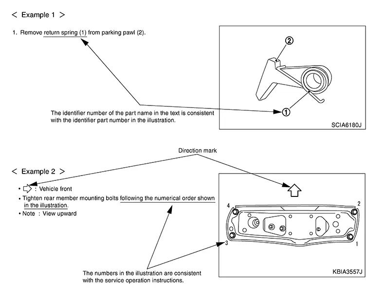
Components
Components
-
THE LARGE ILLUSTRATIONS are exploded views (see the following) and contain tightening torques, lubrication points, section number of the PARTS CATALOG (e.g. SEC. 440) and other information necessary to perform repairs.
The illustrations should be used in reference to service matters only. When ordering parts, refer to the appropriate PARTS CATALOG.
Always check with the PARTS DEPARTMENT for the latest parts information.
Components shown in an illustration may be identified by a circled number. When this style of illustration is used, the text description of the components will follow the illustration.
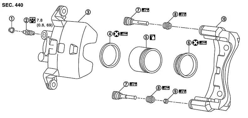
|
1. |
Cap |
2. |
Bleeder valve |
3. |
Cylinder body |
|
4. |
Piston seal |
5. |
Piston |
6. |
Piston boot |
|
7. |
Sliding pin |
8. |
Sliding pin boot |
9. |
Bushing |
|
10. |
Torque member |
||||
|
|
: Apply rubber grease. |
||||
|
|
: Apply brake fluid. |
||||
|
|
: N·m (kg-m, in-lb) |
||||
|
|
: Always replace after every disassembly |
||||


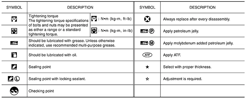
SYMBOLS
Other materials:
Engine Mounting Insulator (rh)
Exploded View
Exploded View
CVT Models
1.
Engine mounting
insulator (LH)
2.
Engine mounting
insula ...
Front Brake Caliper Assembly
Exploded View
Exploded View
1.
Brake caliper body
2.
Bleeder valve
3.
...
Traffic Sign Recognition (TSR)
The Traffic Sign Recognition (TSR) system in the Nissan Sentra provides the driver
with information about the most recently detected speed limit and certain traffic
signs. The system captures road sign data using the multi-sensing front camera unit
(A), which is mounted on the windshield i ...