Nissan Sentra B18 (2020-2025) Service Manual: How to Read Wiring Diagrams
Connector Symbols
Connector symbols
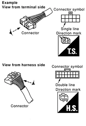
Most of the connector symbols in wiring diagrams are shown from the terminal side.
-
Connector symbols shown from the terminal side are enclosed by a single line and followed by the direction mark.
-
Connector symbols shown from the harness side are enclosed by a double line and followed by the direction mark.
-
Certain systems and components, especially those related to OBD, may use a new style slide-locking type harness connector. For description and how to disconnect, refer to PG section, “Description�, “HARNESS CONNECTOR�.
-
Male and female terminals
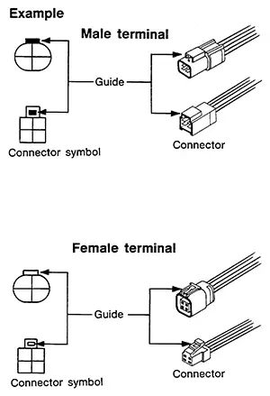
Connector guides for male terminals are shown in black and female terminals in white in wiring diagrams.
Sample/wiring Diagram -Example-
Sample/wiring diagram -example-
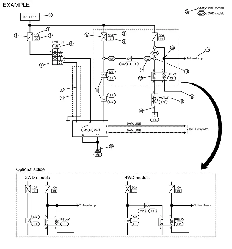
Each section includes wiring diagrams.
|
No. |
Item |
Description |
|
|---|---|---|---|
|
1 |
Power supply |
|
|
|
2 |
Fuse |
|
|
|
3 |
Current rating of fusible link/fuse |
|
|
|
4 |
Number of fusible link/fuse |
|
|
|
5 |
Fusible link |
|
|
|
6 |
Connector number |
|
|
|
7 |
Switch |
|
|
|
8 |
Circuit (Wiring) |
|
|
|
9 |
Shielded line |
|
|
|
10 |
Connectors |
|
|
|
11 |
Option abbreviation |
|
|
|
12 |
Relay |
|
|
|
13 |
Optional splice |
|
|
|
14 |
Splice |
|
|
|
15 |
System branch |
|
|
|
16 |
Page crossing |
|
|
|
17 |
Component name |
|
|
|
18 |
Terminal number |
|
|
|
19 |
Ground (GND) |
|
|
|
20 |
Explanation of option description |
|
|
 �.
�. � means the splice.
SWITCH POSITIONS
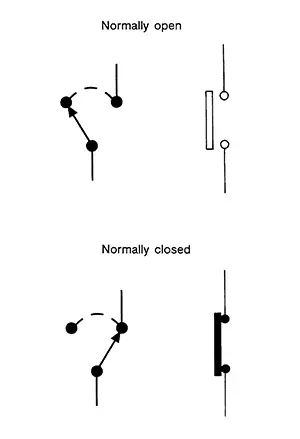
Switches are shown in wiring diagrams as if the Nissan Sentra vehicle is in the “normal� condition.
A vehicle is in the “normal� condition when:
-
Ignition switch OFF
-
Doors, hood and trunk lid/back door are closed
-
Pedals are not depressed
-
Parking brake is released
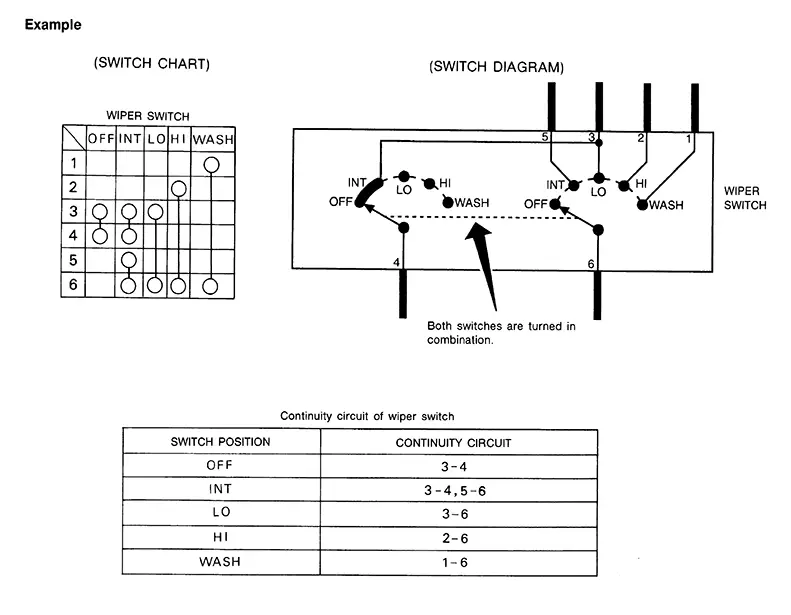
MULTIPLE SWITCH
The continuity of multiple switch is described in two ways as shown below.
-
The switch chart is used in schematic diagrams.
-
The switch diagram is used in wiring diagrams.
Connector Information
Connector Information
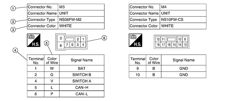
|
No. |
Item |
Description |
|
|---|---|---|---|
|
1 |
Connector number |
|
|
|
2 |
Connector type |
|
 |
|
3 |
Connector color |
|
|
|
4 |
Terminal number |
|
|
|
5 |
Wire color |
|
|
|
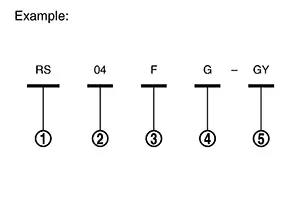
B = Black W = White R = Red G = Green L = Blue Y = Yellow LG = Light Green BG or BE = Beige BR = Brown |
LA = Lavender OR or O = Orange P = Pink PU or V (Violet) = Purple GY or GR = Gray SB = Sky Blue CH = Dark Brown DG = Dark Green |
||
|
|||
|
6 |
Connector |
|
|
 : Connector model
 : Cavity
 : Male (M) and female (F) terminals
 : Connector color
 : Special type
Other materials:
C106b-64 Stop Lamp Switch
Dtc Description
DTC Description
DTC DETECTION LOGIC
DTC No.
CONSULT screen item
(Trouble diagnosis
content)
DTC detection condition
...
Basic Inspection
Diagnosis and Repair Workflow
Work Flow
Work flow
OVERALL SEQUENCE
Reference 1: On Board Diagnosis Function.
Reference 2: DTC Index.
Reference 3: Diagnosis Procedure.
Reference 4: Component Inspection.
Reference 5 ...
Horn. Precaution. Precautions. Precaution for Supplemental Restraint System (srs) "air Bag" and "seat Belt Pre-Tensioner"
Precautions. Precaution for Supplemental Restraint System (srs) "air Bag" and "seat Belt Pre-Tensioner"
Precaution for Supplemental Restraint System (srs) "air Bag" and "seat Belt Pre-Tensioner"
Precaution for Supplemental Restraint System (SRS) "AIR BAG" an ...