Nissan Sentra Service Manual: Fuel tank
Exploded View
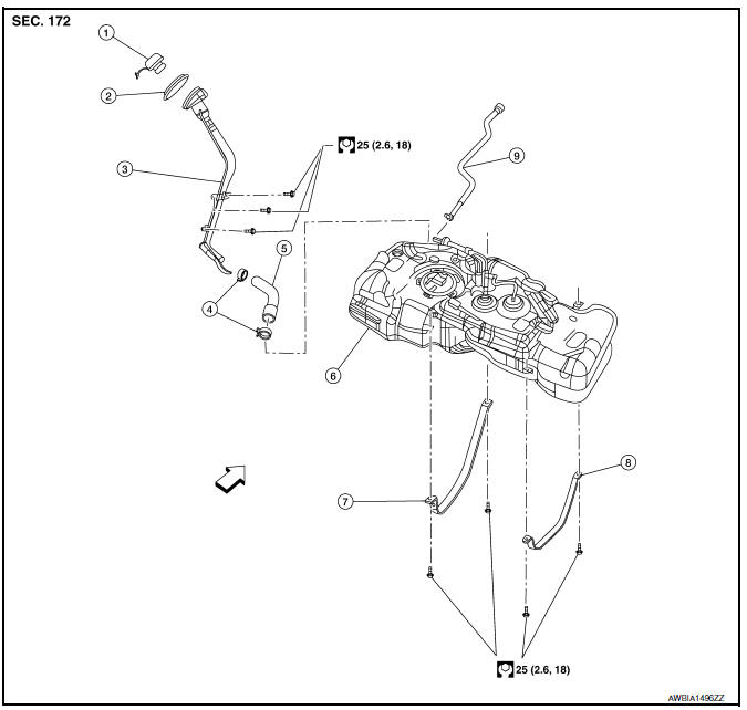
- Fuel filler cap
- Grommet
- Fuel filler tube
- Clamp
- Fuel filler hose
- Fuel tank
- Fuel tank mounting band (RH)
- Fuel tank mounting band (LH)
- Vent hose
Removal and Installation
WARNING:
Be sure to read “General Precautions” when working on the fuel system. Refer to FL-2, "General Precaution".
NOTE:
When removing components such as hoses, tubes/lines, etc., cap or plug openings to prevent fluid from spilling.
REMOVAL
- Open fuel filler lid.
- Open filler cap and release the pressure inside fuel tank.
- Release the fuel pressure from the fuel lines. Refer to EC-143, "Work Procedure".
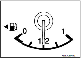
- Check the fuel level with the vehicle on a level surface. If the fuel gauge indicates more than the level as shown (1/2 full), drain the fuel from the fuel tank until the fuel gauge indicates a level at or below as shown (1/2 full).
- In case the fuel pump does not operate, use the following procedure.
- Insert fuel tubing of less than 25 mm (0.98 in) diameter into the fuel filler tube through the fuel filler opening to drain fuel from the fuel filler tube.
- Disconnect the fuel filler hose from the fuel filler tube.
- Insert fuel tubing into the fuel tank through the fuel filler hose to drain fuel from the fuel tank.
- As a guide, if the fuel tank is full the fuel level reaches or is less
than the level on the fuel gauge as
shown, when approximately 25

(6-5/8 US gal, 5-1/2 Imp gal) of fuel is drained from a full fuel tank.
- Disconnect park brake rear cables and position the rear park brake cables aside. Refer to PB-7, "Exploded View".
- Remove the tunnel stay, front exhaust tube and sub muffler. Refer to EX-5, "Removal and Installation".
- Remove trunk floor carpet. Refer to INT-43, "TRUNK SIDE FINISHER : Removal and Installation".
- Remove rear seat cushion assembly. Refer to SE-23, "Removal and Installation - Seat Cushion Assembly".
- Remove inspection hole cover.
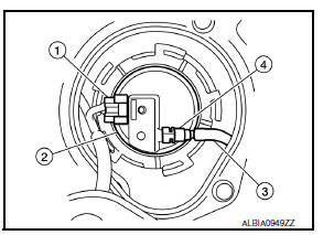
- Disconnect harness connector (1), fuel feed hose (3), and quick connector (4) from fuel level sensor unit, fuel filter and fuel pump assembly (2).
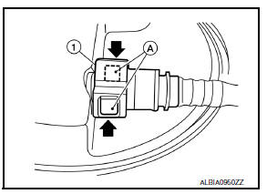
- Remove quick connector in the following procedures.
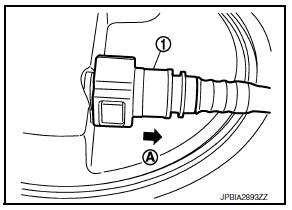
- Pinch quick connector square-part (A) with your fingers, and pull out the quick connector (1) by hand.
- If quick connector and tube on sender unit are stuck, push and pull several times until they move, and pull out.
CAUTION:
- Quick connector can be removed when the tabs are completely depressed. Do not twist it more than necessary.
- Do not use any tools to disconnected quick connector.
- Keep resin tube away from heat. Be especially careful when welding near the resin tube.
- Prevent acid liquid such as battery electrolyte, etc. from getting on resin tube.
- Do not bend or twist resin tube during installation and disconnection.
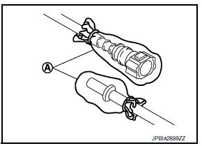
- To keep the connecting portion clean and to avoid damage and foreign materials, cover them completely with plastic bags (A) or something similar.
- Do not insert plug, preventing damage on O-ring in quick connector.
- Remove the tunnel stay and center exhaust tube, without muffler. Refer to EX-5, "Exploded View".
- Remove the fuel tank protector.
- Disconnect the rear cables and position the rear cables aside. Refer to BR-42, "Exploded View" (Drum brake) or PB-9, "Exploded View - Disc Brake" (Disc brake).
- Disconnect return line from filler hose.
- Remove fuel filler hose.
- Disconnect vent hose from fuel tank.
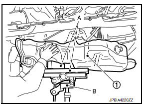
- Support the center of the fuel tank (1) with a suitable jack (B) and secure the fuel tank to the jack.
CAUTION:
- Securely support the fuel tank with a piece of wood (A).
- Fuel tank may be in an unstable condition, due to the shape of the fuel tank bottom. Be sure to secure tank at all times.
- Remove fuel tank mounting bands (RH/LH).
- Lower suitable jack carefully to remove fuel tank while holding it by hand.
CAUTION:
Fuel tank may be in an unstable condition, due to the shape of the fuel tank bottom. Be sure to secure tank at all times.
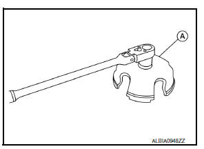
- Remove lock ring for fuel level sensor unit, fuel filter and fuel pump assembly with Tool (A) by turning counterclockwise (if necessary).
Tool number (A) : KV991J0090 (J-46214) (shown) : KV101208S0 ( — )
- Remove fuel level sensor unit, fuel filter and fuel pump assembly (if necessary).
CAUTION:
- Do not bend float arm during removal.
- Do not pollute the inside by residue fuel. Draw out avoiding inclination by supporting with a cloth.
- Do not cause impacts such by dropping when handling components
INSTALLATION
Installation is in the reverse order of removal.
NOTE:
- Do not use any lubrication to aid with the installation of tubes and hoses.
- Before tightening the fuel tank mounting bands, install the filler hose to the length of 35 mm (1.38 in), all other hoses to 25 mm (0.98 in).
- Tighten the clamps until the head of the bolt is on the paint mark on the clamp band.
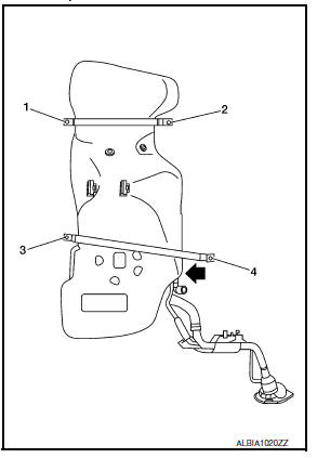
- Tight mounting band bolts 1 and 2 to specification. Hand tighten mounting band bolt 3. While pushing the tank in the direction shown, tighten mounting band bolt 4 to specification then mounting band bolt 3.
Quick Connector
- Connect quick connector as follows:
- Check the connection for damage or any foreign materials.
- Align the connector with the tube, then insert the connector straight into the tube until a click sound is heard.
- After connecting, check that the connection is secure by following method.
- Visually confirm that the two tabs are connected to the connector.
- Pull (A) the tube and the quick connector (1) to check they are securely connected.
Inspection
INSPECTION AFTER INSTALLATION
Use the following procedure to check for fuel leaks.
- Turn ignition switch “ON” (with engine stopped), then check connections for leaks by applying fuel pressure to fuel piping.
- Start engine and let it idle and check there are no fuel leaks at the fuel system connections.
 Fuel level sensor unit, fuel filter and fuel pump assembly
Exploded View
Lock ring
Fuel level sensor, fuel filter and fuel
pump assembly
O-ring
Fuel tank
Removal and Installation
WARNING:
Read “General Precautions” when working ...
 Evap canister
Exploded View
EVAP canister bracket
EVAP canister filter drain hose
EVAP canister filter
EVAP canister protector
EVAP hose
EVAP canister vent control valve
O-ring
EVAP canister
...
Other materials:
On board diagnosis function
ON BOARD DIAGNOSIS ITEM
The on board diagnostic system has the following functions.
Diagnostic test mode
Function
Bulb check
MIL can be checked.
SRT status
ECM can read if SRT codes are set.
Malfunction warning
If ECM detects a malfunction, it illumina ...
Preparation
Special Service Tools
The actual shape of the tools may differ from those illustrated here.
Commercial Service Tools
...
Illumination control switch
Removal and installation
Removal
Remove instrument finisher d. Refer to ip-14, "exploded view".
Remove the illumination control switch (1) from the switch carrier
(2) using suitable tool (a).
: Pawl
Installation
Installation is in the reverse order of removal. ...
