Nissan Sentra Service Manual: Fuel level sensor unit, fuel filter and fuel pump assembly
Exploded View
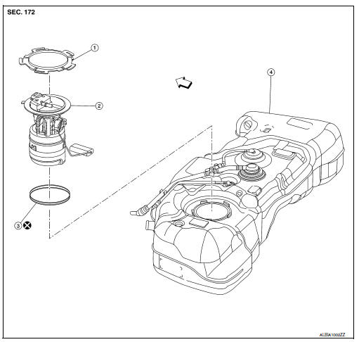
- Lock ring
- Fuel level sensor, fuel filter and fuel pump assembly
- O-ring
- Fuel tank
Removal and Installation
WARNING:
Read “General Precautions” when working on the fuel system. Refer to FL-2, "General Precaution".
NOTE:
When removing components such as hoses, tubes/lines, etc., cap or plug openings to prevent fluid from spilling.
REMOVAL
- Release the fuel pressure from the fuel lines. Refer to EC-143, "Work Procedure".
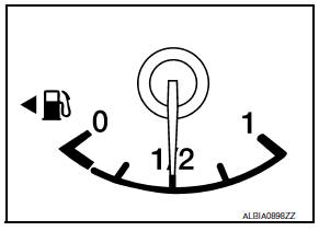
- Check the fuel level with the vehicle on a level surface. If the fuel gauge indicates more than the level as shown (1/2 full), drain the fuel from the fuel tank until the fuel gauge indicates a level at or below as shown (1/2 full).
- In case the fuel pump does not operate, use the following procedure.
- Insert fuel tubing of less than 25 mm (0.98 in) diameter into the fuel filler tube through the fuel filler opening to drain fuel from the fuel filler tube.
- Disconnect the fuel filler hose from the fuel filler tube.
- Insert fuel tubing into the fuel tank through the fuel filler hose to drain fuel from the fuel tank.
- As a guide, if the fuel tank is full the fuel level reaches or is less than the level on the fuel gauge as shown, when approximately 25 (6-5/8 US gal, 5-1/2 Imp gal) of fuel is drained from a full fuel tank.
- Open fuel filler lid.
- Remove trunk floor carpet. Refer to INT-43, "TRUNK SIDE FINISHER : Removal and Installation".
- Open filler cap and release the pressure inside fuel tank.
- Remove rear seat cushion assembly. Refer to SE-23, "Removal and Installation - Seat Cushion Assembly".
- Remove inspection hole cover.
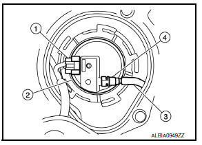
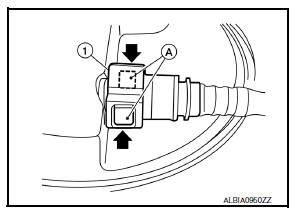
- Disconnect harness connector (1), fuel feed hose (3) and quick connector (4) from fuel level sensor unit, fuel filter and fuel pump assembly (2).
- Remove quick connector in the following procedures.
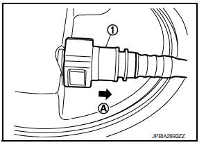
- Pinch quick connector square-part (A) with your fingers, and pull out the quick connector (1) by hand.
- If quick connector and tube on sender unit are stuck, push and pull several times until they move, and pull out.
CAUTION:
- Quick connector can be removed when the tabs are completely depressed. Do not twist it more than necessary.
- Do not use any tools to disconnected quick connector
- Keep resin tube away from heat. Be especially careful when welding near the resin tube.
- Prevent acid liquid such as battery electrolyte, etc. from getting on resin tube.
- Do not bend or twist resin tube during installation and disconnection.
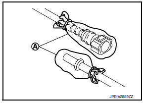
- To keep the connecting portion clean and to avoid damage and foreign materials, cover them completely with plastic bags (A) or something similar.
- Do not insert plug, preventing damage on O-ring in quick connector.
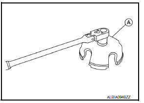
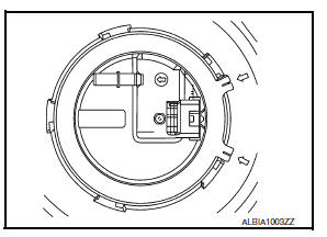
- Remove lock ring for fuel level sensor unit, fuel filter and fuel pump assembly with Tool (A) by turning counterclockwise.
Tool number (A) : KV991J0090 (J-46214) (shown) : KV101208S0 ( — )
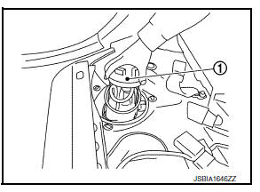
- Remove fuel level sensor unit, fuel filter and fuel pump assembly (1).
CAUTION:
- Do not bend float arm during removal.
- Place a cloth around the fuel level sensor, fuel fitler and fuel pump assembly during removal to avoid spilling fuel inside the vehicle.
- Do not cause impacts such by dropping when handling components.
INSTALLATION
Installation is in the reverse order of removal.
- Install the O-ring to the opening of the fuel tank.
CAUTION:
Do not reuse O-ring.
- Insert the fuel level sensor unit, fuel filter and fuel pump assembly to the fuel tank with its matching arrow aligned with fuel tank matching arrow.
CAUTION:
- Do not bend float arm during installation.
NOTE:
For fuel level sensor assembly matching mark is located on the fuel tank to the rear side of the vehicle.
- Install Lock ring with Tool (A) to tighten lock ring.
Tool number (A) : KV991J0090 (J-46214) (shown) : KV101208S0 ( — )
Quick Connector
Connect quick connector as follows:
- Check the connection for damage or any foreign materials.
- Align the connector with the tube, then insert the connector straight into the tube until a click sound is heard.
- After connecting, check that the connection is secure by following method.
- Visually confirm that the two tabs are connected to the connector.
- Pull (A) the tube and the quick connector (1) to check they are securely connected.
Inspection
INSPECTION AFTER INSTALLATION
Use the following procedure to check for fuel leaks.
- Turn ignition switch “ON” (with engine stopped), then check connections for leaks by applying fuel pressure to fuel piping.
- Start engine and let it idle and check there are no fuel leaks at the fuel system connections.

 Fuel tank
Exploded View
Fuel filler cap
Grommet
Fuel filler tube
Clamp
Fuel filler hose
Fuel tank
Fuel tank mounting band (RH)
Fuel tank mounting band (LH)
Vent hose
Removal and Insta ...
Other materials:
Precaution for Supplemental Restraint System (SRS) "AIR BAG" and "SEAT BELT
PRE-TENSIONER"
The Supplemental Restraint System such as “AIR BAG” and “SEAT BELT PRE-TENSIONER”,
used along
with a front seat belt, helps to reduce the risk or severity of injury to the
driver and front passenger for certain
types of collision. Information necessary to service the system ...
Brake pedal
Inspection
BRAKE PEDAL HEIGHT
Check the brake pedal height (H1) between the dash lower panel (1)
and the brake pedal upper surface.
Brake pedal height (H1) : Refer to BR-54, "Brake Pedal".
CAUTION:
Check the brake pedal height with the floor trim removed.
STOP LAMP SWITCH AND BR ...
Ecu diagnosis information
ECM
Reference Value
VALUES ON THE DIAGNOSIS TOOL
NOTE:
The following table includes information (items) inapplicable to this
vehicle. For information (items) applicable
to this vehicle, refer to CONSULT display items.
Numerical values in the following table are reference values.
Thes ...
