Nissan Sentra Service Manual: Basic inspection
Diagnosis and repair workflow
Work flow
OVERALL SEQUENCE
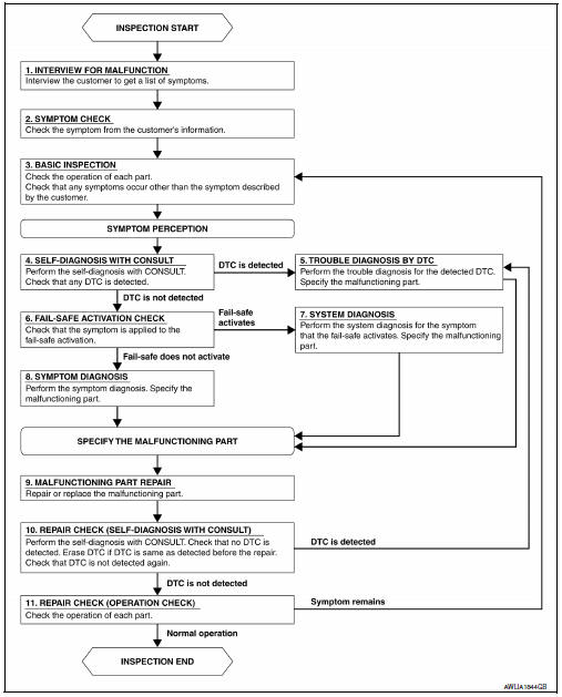
DETAILED FLOW
1.INTERVIEW FOR MALFUNCTION
Find out what the customer's concerns are.
>> GO TO 2.
2.SYMPTOM CHECK
Verify the symptom from the customer's information.
>> GO TO 3.
3.BASIC INSPECTION
Check the operation of each part. Check that any concerns occur other than those mentioned in the customer interview.
>> GO TO 4.
4.SELF-DIAGNOSIS WITH CONSULT
Perform the self-diagnosis with CONSULT. Check that any DTC is detected.
Is any DTC detected? YES >> GO TO 5.
NO >> GO TO 6.
5.TROUBLE DIAGNOSIS BY DTC
Perform the trouble diagnosis for the detected DTC. Specify the malfunctioning part.
>> GO TO 9.
6.FAIL-SAFE ACTIVATION CHECK
Determine if the customer's concern is related to fail-safe activation.
Does the fail-safe activate? YES >> GO TO 7.
NO >> GO TO 8.
7.SYSTEM DIAGNOSIS
Perform the system diagnosis for the system in which the fail-safe activates. Specify the malfunctioning part.
>> GO TO 9.
8.SYMPTOM DIAGNOSIS
Perform the symptom diagnosis, refer to INL-51, "Symptom Table". Specify the malfunctioning part.
>> GO TO 9.
9.MALFUNCTION PART REPAIR
Repair or replace the malfunctioning part.
>> GO TO 10.
10.REPAIR CHECK (SELF-DIAGNOSIS WITH CONSULT)
Perform the self-diagnosis with CONSULT. Verify that no DTCs are detected. Erase all DTCs detected prior to the repair. Verify that DTC is not detected again.
Is any DTC detected? YES >> GO TO 5.
NO >> GO TO 11.
11.REPAIR CHECK (OPERATION CHECK)
Check the operation of each part.
Does it operate normally? YES >> Inspection End.
NO >> GO TO 3.
 Wiring diagram
Interior room lamp control system
Wiring diagram
Illumination
Wiring diagram
...

Other materials:
Maintenance precautions
When performing any inspection or maintenance
work on your vehicle, always take care to prevent
serious accidental injury to yourself or damage to
the vehicle. The following are general precautions
which should be closely observed.
WARNING
Park the vehicle on a level surface, apply
...
Wiring diagram
Display audio with bose
Wiring diagram
...
Excessive abs function operation
frequency
Diagnosis Procedure
1.CHECK START
Check front and rear brake force distribution using a brake
tester.
Is the inspection result normal?
YES >> GO TO 2
NO >> Check brake system.
2.CHECK FRONT AND REAR AXLE
Make sure that there is no excessive play in the front and rear
axles. ...
