Nissan Sentra B18 (2020-2025) Service Manual: Fuel Tank
Exploded View
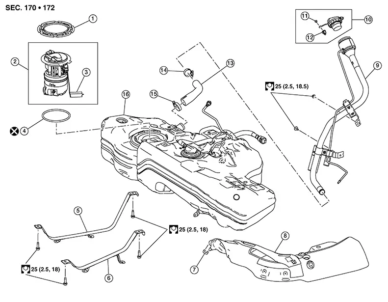
Exploded View
|
1. |
Fuel pump locking ring |
2. |
Fuel pump assembly |
3. |
Fuel level sensor |
|
4. |
Fuel pump o-ring |
5. |
Fuel tank mounting strap (RH) |
6. |
Fuel tank mounting strap (LH) |
|
7. |
Fuel tank protector clip) |
8. |
Fuel tank protector |
9. |
Fuel filler tube assembly |
|
10. |
Fuel cap assembly |
11. |
fuel cap tether clip |
12. |
fuel cap tether grommet |
|
13. |
fuel filler tube |
14. |
fuel filler tube band clamp |
15. |
Tank side band clamp |
|
16. |
Fuel tank |
Removal and Installation
Removal and Installation
Warning:
Be sure to read ŌĆ£General PrecautionsŌĆØ when working on the fuel system. Refer to General Precaution .
Note:
When removing components such as hoses, tubes/lines, etc., cap or plug openings to prevent fluid from spilling.
REMOVAL
Open fuel filler lid.
Open filler cap and release the pressure inside fuel tank.
Release the fuel pressure from the fuel lines. Refer to Work Procedure.
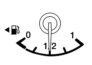
Check the
fuel level with the Nissan Sentra vehicle on a level surface. If the fuel gauge
indicates more than the level as shown (1/2 full), drain the fuel
from the fuel tank until the fuel gauge indicates a level at or
below as shown (1/2 full).
-
In case the fuel pump does not operate, use the following procedure.
-
As a guide, if the fuel tank is full, drain approximately 23-1/2
 (6-1/5 US gal, 5-1/10 Imp gal)to reach 1/2 full or less.
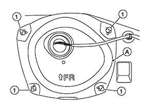
Remove rear seat cushion assembly. Refer to Removal and Installation - Seat Cushion Assembly.
Remove
inspection hole cover.
Disconnect harness connector, fuel feed hose, and quick connector from fuel level sensor unit, fuel filter and fuel pump assembly.
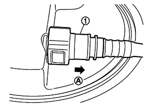
-
Remove quick connector in the following procedures.
-
Pinch quick connector square-part (A) with your fingers, and pull out the quick connector (1) by hand.
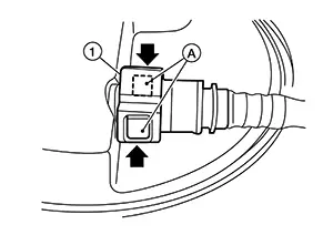
-
If quick connector and tube on sender unit are stuck, push and pull several times until they move, and pull out.
-
CAUTION:
-
Quick connector can be removed when the tabs are completely depressed. Do not twist it more than necessary.
-
Do not use any tools to disconnected quick connector.
-
Keep resin tube away from heat. Be especially careful when welding near the resin tube.
-
Prevent acid liquid such as battery electrolyte, etc. from getting on resin tube.
-
Do not bend or twist resin tube during installation and disconnection.
-
To keep the connecting portion clean and to avoid damage and foreign materials, cover them completely with plastic bags (A) or something similar.
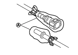
-
Do not insert plug, preventing damage on O-ring in quick connector.
Remove exhaust main muffler. Refer to Exploded View.
Remove the fuel tank protector.
Disconnect return line from filler hose.
Remove fuel filler hose.
Disconnect vent hose from fuel tank.
Support the
center of the fuel tank (1) with a suitable jack (B) and secure the
fuel tank to the jack.
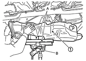
CAUTION:
-
Securely support the fuel tank with a piece of wood (A).
-
Fuel tank may be in an unstable condition, due to the shape of the fuel tank bottom. Be sure to secure tank at all times.
Remove fuel tank mounting bands (RH/LH).
Lower suitable jack carefully to remove fuel tank while holding it by hand.
CAUTION:
Fuel tank may be in an unstable condition, due to the shape of the fuel tank bottom. Be sure to secure tank at all times.
Remove lock ring for fuel level sensor unit, fuel filter and fuel pump assembly with Tool (A) by turning counterclockwise (if necessary).
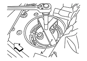
|
Tool number (A) |
: KV991J0090 (NI-45747) (shown) |
|
: KV101207S0 (ŌĆāŌĆöŌĆā) |
Remove fuel level sensor unit, fuel filter and fuel pump assembly (if necessary).
CAUTION:
-
Do not bend float arm during removal.
-
Do not pollute the inside by residue fuel. Draw out avoiding inclination by supporting with a cloth.
-
Do not cause impacts such by dropping when handling components.
INSTALLATION
Installation is in the reverse order of removal.
Note:
-
Do not use any lubrication to aid with the installation of tubes and hoses.
-
Before tightening the fuel tank mounting bands, install the filler hose to the length of 35 mm (1.38 in), all other hoses to 25 mm (0.98 in).
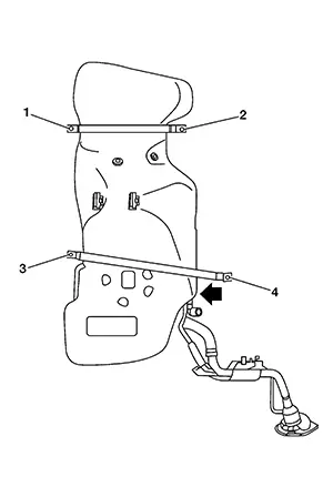
-
Tighten the clamps until the head of the bolt is on the paint mark on the clamp band.
-
Tight mounting band bolts (1) and (2) to specification. Hand tighten mounting band bolt (3). While pushing the tank in the direction shown, tighten mounting band bolt (4) to specification then mounting band bolt (3).
Quick Connector
Connect quick connector as follows:
Check the connection for damage or any foreign materials.
Align the connector with the tube, then insert the connector straight into the tube until a click sound is heard.
After connecting, check that the connection is secure by following method.
-
Visually confirm that the two tabs are connected to the connector.
-
Pull (A) the tube and the quick connector (1) to check they are securely connected.
Inspection
Inspection
INSPECTION AFTER INSTALLATION
Use the following procedure to check for fuel leaks.
Place ignition to ŌĆ£ONŌĆØ position (with engine stopped), then check connections for leaks by applying fuel pressure to fuel piping.
Start engine and let it idle and check there are no fuel leaks at the fuel system connections.
Other materials:
Remote Keyless Entry Function
System Diagram
System Diagram
System Description
System Description
The Intelligent Key has the same functions as the
remote control entry system. Therefore, it can be used in the same
manner as the remote controller by operating the door lock/unlock
button.
OPERATION
Re ...
C1714-7b Low Tire Pressure Rr
Dtc Description
DTC Description
Note:
The Signal Tech II Tool [ŌĆō (NI-50190)] can be used
to perform the following functions: Refer to the Signal Tech II User
Guide for additional information.
Activate and display TPMS sensor IDs
Display tire pressure rep ...
B24d4-08 A/c Control Comm
Dtc Description
DTC Description
DTC DETECTION LOGIC
DTC No.
CONSULT screen terms
(Trouble diagnosis content)
DTC detection condition
...