Nissan Sentra B18 (2020-2025) Service Manual: Fuel Injector and Fuel Tube
Exploded View
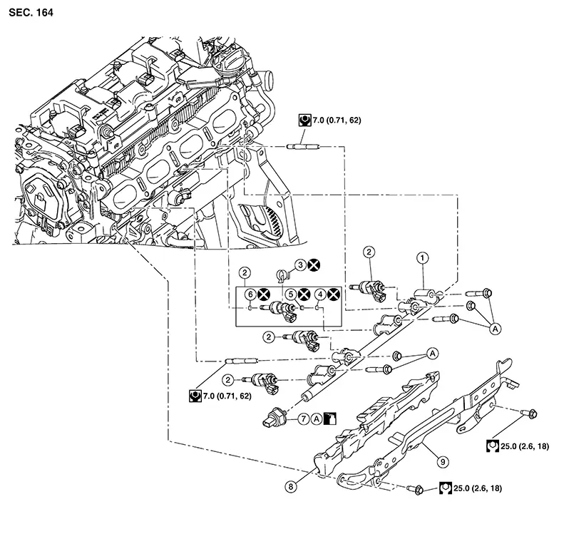
Exploded View
|
1. |
High pressure fuel rail |
2. |
Fuel injector assembly |
3. |
Injector holder |
|
4. |
O-ring (black) |
5. |
Backup ring |
6. |
Seal ring |
|
7. |
Fuel rail pressure sensor |
8. |
Fuel rail insulator |
9. |
High pressure fuel rail protector |
|
B. |
Refer to Removal and Installation. |
CAUTION:
Do not remove or disassemble parts unless instructed as shown.
Removal and Installation
Removal and Installation
Warning:
-
Be sure to read Precaution for Handling High Pressure Fuel System when working on the high pressure fuel system.
-
Put a “CAUTION: FLAMMABLE” sign in the workshop.
-
Be sure to work in a well ventilated area and furnish workshop with a CO2 fire extinguisher.
-
Do not smoke while servicing fuel system. Keep open flames and sparks away from the work area.
-
To avoid the danger of being scalded, do not drain engine coolant when engine is hot.

When removing components such as hoses, tubes/lines, etc., cap or plug openings to prevent fluid from spilling.
REMOVAL
Release the fuel pressure. Refer to Work Procedure.
Disconnect the battery. Refer to Battery Disconnect.
Remove the intake manifold. Refer to Removal and Installation.
Remove the high pressure fuel rail protector.
Remove high pressure fuel tube. Refer to Exploded View.
Remove the high pressure fuel rail insulator.
Disconnect the harness connector from the fuel rail pressure sensor.
Disconnect the harness connectors from the fuel injector assemblies.
Remove the fuel rail pressure sensor (if necessary).
Loosen high
pressure fuel rail nuts and bolts in reverse of the sequence shown
and remove the high pressure fuel rail.
CAUTION:
-
When removing, be careful to avoid any interference with fuel injector.
-
Use a shop cloth to absorb any fuel that leaks from high pressure fuel rail.
If fuel injectors remain in cylinder head after removing high pressure fuel rail, remove the fuel injectors using the following procedure:
CAUTION:
-
Be careful with remaining fuel that may go out from high pressure fuel rail.
-
Be careful not to damage injector nozzles during removal.
-
Do not bump or drop fuel injector.
-
Do not disassemble fuel injector.
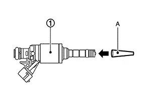
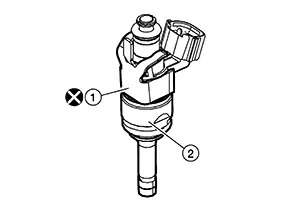
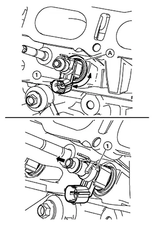 Rotate fuel injector assembly (1)
back and forth to allow suitable lubricant to seep into
bore. Pull
straight out on fuel injector assembly to remove from cylinder
head.
Rotate fuel injector assembly (1)
back and forth to allow suitable lubricant to seep into
bore. Pull
straight out on fuel injector assembly to remove from cylinder
head.
Remove O-ring, backup ring and injector holder from fuel injector.
CAUTION:
Do not reuse O-ring, backup ring or injector holder.
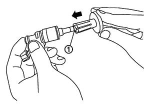
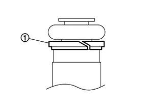
Cut seal
ring (1) while pinching it. 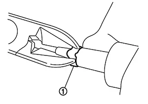
CAUTION:
-
Do not scratch fuel injector when removing seal ring.
-
Do not reuse seal ring.
Remove the high pressure fuel rail studs from the cylinder head (if necessary).
INSTALLATION
CAUTION:
Do not reuse O-ring, backup ring, seal ring or injector holder.
Install high pressure fuel rail studs to the cylinder head (if necessary).
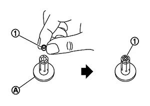
Install seal ring to fuel injector using the following procedure:
CAUTION:
-
Handle seal ring with bare hands. Do not wear gloves.
-
Do not apply engine oil to seal ring.
-
Do not clean seal ring with solvent.
|
Tool number (A) |
: KV10119720 (NI-50364) |
|
Tool number (A) |
: KV10119730 (NI-50364) |
CAUTION:
Be careful that seal ring does not exceed the groove portion of fuel injector.
Insert Tool (A) to fuel injector and rotate clockwise and counterclockwise by 90° while pressing seal ring to fit it.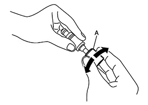 Note:
Note:
This is done to correct any elongation of the seal ring caused by installation and for preventing sticking when inserting fuel injector into cylinder head.
|
Tool number (A) |
: KV10119710 (NI-50364) |
Install O-ring and backup ring to fuel injector.
CAUTION:
-
Do not reuse O-ring.
-
Handle O-ring with bare hands. Do not wear gloves.
-
Lubricate O-ring with new engine oil.
-
Do not clean O-ring with solvent.
-
Check that O-ring and its mating part are free of foreign material.
-
When installing O-ring , be careful not to scratch it with tool or fingernails. Also be careful not to twist or stretch O-ring . If O-ring was stretched while it was being attached, do not insert it quickly into high pressure fuel rail.
-
Insert new O-ring straight into high pressure fuel rail. Do not decenter or twist it.
-
Always install the back up ring (1) in the right direction as instructed.
Install the
fuel injectors to the high pressure fuel rail using the following
procedure:
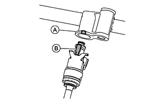
Install the injector holder (1) onto
the fuel injector (2).
CAUTION:
-
Do not reuse injector holder.
-
Be careful to keep injector holder from interfering with O-ring. If interference occurs, replace O-ring.
-
Insert it while matching it to the axial center.
-
Insert so that tab (B) of injector holder is aligned to cutout (A) of high pressure fuel rail.
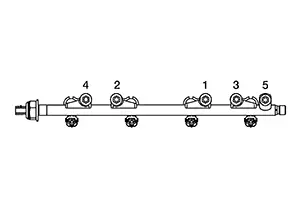
Install
high pressure fuel rail and fuel injector assembly to cylinder head
and tighten nuts and bolts to the specified torque in the sequence
shown.
|
Step 1 |
: 10.0 N·m (1.0 kg-m, 89 in-lb) |
|
Step 2 |
: 25 N·m (2.6 kg-m, 18 ft-lb) |
Install the fuel rail pressure sensor using the following procedure (if necessary): Apply engine oil to the entire perimeter of the fuel pressure sensor screw.
CAUTION:
Check that high pressure fuel rail and fuel pressure sensor screw have no damage, foreign matter, or stains.
Tighten fuel rail pressure sensor to the specified torque.CAUTION:
-
Before tightening fuel rail pressure sensor, securely install a hexagon tool.
-
Do not use fuel rail pressure sensor that has been dropped.
|
Fuel rail pressure sensor |
: 10.0 N·m (1.0 kg-m, 89 in-lb) |
CAUTION:
-
To check tightening angle, use Tool. Do not judge the angle by visual inspection.
-
The torque value for the angle tightening must be less than 60 N·m (6.1 kg-m, 44 ft-lb).
-
If torque value reaches 60 N·m (6.1 kg-m, 44 ft-lb), then replace the fuel rail pressure sensor and high pressure fuel rail with a new one.
|
Tool number |
: KV10112100 (BT-8653-A) |
|
Tightening angle |
: 35° - 40° |
Installation of the remaining components is in the reverse order of removal.
Inspection
Inspection
INSPECTION AFTER INSTALLATION
Check on Fuel Leaks
Place
ignition switch in the “ON” position (with the engine
stopped). With fuel pressure applied to fuel piping, check there
are no fuel leaks at connection points.
Note:
Use mirrors for checking at points out of clear sight.
Start the engine. With engine speed increased, check again that there are no fuel leaks at connection points.
CAUTION:
Do not touch the engine immediately after stopped, as the engine becomes extremely hot.
Other materials:
Clutch. Removal and Installation
Clutch Pedal
Exploded View
Exploded View
1.
Clutch pedal
2.
Clutch master cylinder
...
Intelligent Key Button Operation Has Poor Range (one Key)
Description
Description
Intelligent Key button operation has poor range.
(One Intelligent Key has the symptom, other keys operate
normally.)
SYMPTOM TABLE (ONE INTELLIGENT KEY HAS THE
SYMPTOM, OTHER KEYS OPERATE NORMALLY)
...
Engine Mounting Insulator (rh)
Exploded View
Exploded View
CVT Models
1.
Engine mounting
insulator (LH)
2.
Engine mounting
insula ...