Nissan Sentra B18 (2020-2025) Service Manual: Front Suspension :: Unit Disassembly and Assembly. Front Coil Spring and Strut
Front Coil Spring and Strut. Exploded View
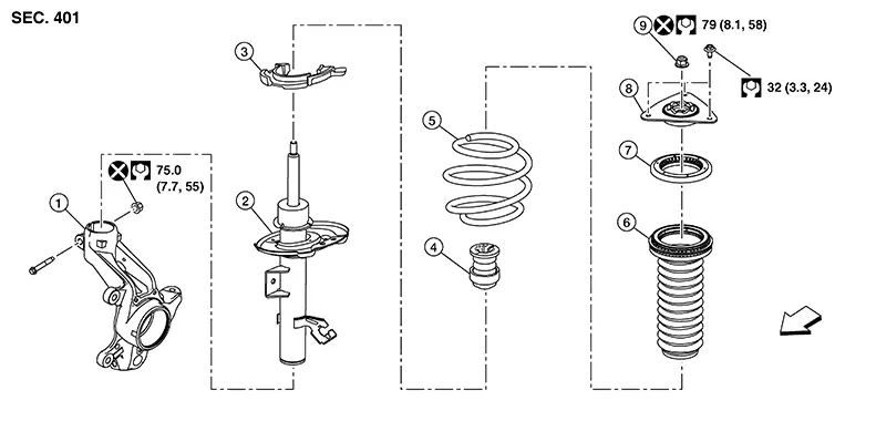
Exploded View
|
1. |
Steering knuckle |
2. |
Strut |
3. |
Lower rubber seat |
|
4. |
Bound bumper |
5. |
Coil spring |
6. |
Dust cover |
|
7. |
Mounting bearing |
8. |
Mounting insulator |
9. |
Piston rod lock nut |
|
|
Front |
Disassembly and Assembly
Disassembly and Assembly
DISASSEMBLY
CAUTION:
Do not damage the piston rod when removing components from the front coil spring and strut.
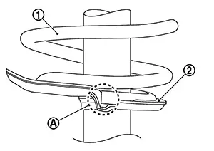
Install
Tool (A) to the front coil spring and strut. 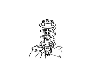
CAUTION:
When installing Tool (A), wrap a shop cloth around the front coil spring and strut to protect the parts from damage.
|
Tool number |
(A) : ST35652000 ( — ) |
Secure Tool (A) in a vise.
Slightly loosen the piston rod lock nut.
Warning:
Do not remove the piston rod lock nut completely. If the piston rod lock nut is removed completely, the coil spring can jump out and may cause serious damage or injury.
Compress
the coil spring using a suitable tool (A).
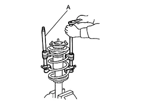
Warning:
Make sure that the pawls of the suitable tool are firmly hooked on the coil spring. The suitable tool must be tightened alternately so as to not tilt the coil spring.
Make sure the coil spring is free between the strut mount insulator and the lower rubber seat.
Hold the piston rod and remove the piston rod lock nut.
Remove the strut mount insulator, the strut mount bearing, and the bound bumper from the strut.
Gradually release the suitable tool and remove the coil spring.
CAUTION:
Release the suitable tool while making sure the position of the suitable tool on the coil spring does not move.
Remove the lower rubber seat.
Inspect the components. Refer to Inspection.
ASSEMBLY
CAUTION:
Do not damage the piston rod when removing components from the front coil spring and strut.
Install the lower rubber seat to the strut.
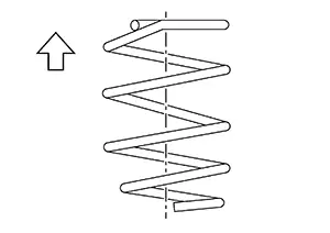
Identify
the upper side of the coil spring.
|
|
: Upper side |
Compress the coil spring using a suitable tool.
Warning:
Make sure that the pawls of the suitable tool are firmly hooked on the coil spring. The suitable tool must be tightened alternately so as to not tilt the coil spring.
Align the
lower end of the coil spring (1) with the lower rubber seat (2) as
shown.
|
Maximum Gap (A) |
: 5 mm (0.2 in) |
Apply soapy water to the bound bumper.
CAUTION:
Do not use machine oil.
Install the bound bumper to the strut.
Install the strut mount bearing to the coil spring.
CAUTION:
Do not apply oil, such as grease, when installing the strut mount bearing.
Set the
mounting insulator (1) to the direction shown in the figure. 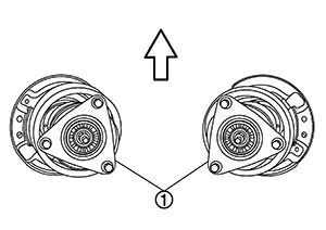
 :Front
Secure the piston rod tip so that the piston rod does not turn. Install the piston rod lock nut and tighten to the specified torque.
CAUTION:
Do not reuse piston rod lock nut.
Gradually
release the suitable tool (A) and remove the suitable tool from the
coil spring.
CAUTION:
Release the suitable tool while making sure the position of the suitable tool on the coil spring does not move.
Remove Tool
(A) from the vise.
|
Tool number |
(A) : ST35652000 ( — ) |
Remove Tool (A) from the front coil spring and strut.
After replacing the strut, always follow the disposal procedure to discard the old strut. Refer to Disposal.
Inspection
Inspection
INSPECTION AFTER DISASSEMBLY
Check the following items and replace the parts if necessary.
Strut
-
Check the strut for oil leaks, deformation, cracks, or damage.
-
Check the piston rod for damage, uneven wear, or distortion.
Strut Mount Insulator and bound bumper
Check the strut mount insulator and the bound bumper for cracks, wear, or damage.
Coil Spring
Check the coil spring for cracks, wear, or damage.
INSPECTION AFTER INSTALLATION
Check the wheel sensor harness to be sure the connectors are fully seated.
Check the neutral position of the steering angle sensor. Refer to Description.
Check the wheel alignment. Refer to Inspection.
Disposal
Disposal
Set the strut horizontally with the piston rod fully extended.
Drill a 2
– 3 mm (0.08 – 0.12 in) hole at the position ( )
from top as shown to release gas gradually.
)
from top as shown to release gas gradually. 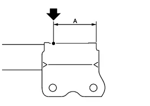
CAUTION:
-
Wear eye protection (safety glasses).
-
Wear gloves.
-
Be careful with metal chips or oil blown out by the compressed gas.

-
Drill vertically in this direction (
 )
directly to the outer tube avoiding brackets.
)
directly to the outer tube avoiding brackets. -
The gas is clear, colorless, odorless, and harmless.
|
(A) |
: 20 – 30 mm (0.79 – 1.18 in) |
Position the drilled hole downward and drain oil by moving the piston rod several times.
CAUTION:
Dispose of drained oil according to the law and local regulations.
Other materials:
System
Intelligent Cruise Control
System Description
System Description
SYSTEM DIAGRAM
Component
Description
ECM
Component
...
Rear Bumper
Exploded View
Exploded View
EXCEPT FOR SR
1.
Rear bumper side bracket (LH)
2.
Rear bumper reinforcement support
(L ...
B20c7-15 A/c Clutch
Dtc Description
DTC Description
DTC DETECTION LOGIC
DTC No.
CONSULT screen terms
(Trouble diagnosis content)
DTC detection condition
...