Nissan Sentra Service Manual: Front drive shaft boot
Exploded View
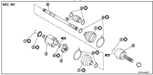
(LH)
- Circular clip
- Dust shield
- Slide joint housing
- Snap ring
- Spider assembly
- Boot band
- Boot
- Shaft
- Damper band
- Dynamic damper
- Circular clip
- Joint sub-assembly
 Wheel side
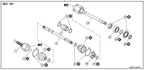
(RH) 6M/T
- Joint sub-assembly
- Circular clip
- Boot band
- Boot
- Shaft
- Damper band
- Dynamic damper
- Boot band
- Boot
- Spider assembly
- Snap ring
- Slide joint housing
- Dust shield
- Support bearing
- Snap ring
- Dust shield
 Wheel side
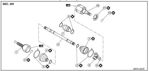
(RH) Except 6M/T
- Joint sub-assembly
- Circular clip
- Boot band
- Boot
- Shaft
- Damper band
- Dynamic damper
- Spider assembly
- Snap ring
- Slide joint housing
- Dust shield
- Circular clip
 Wheel side
 Front wheel hub
Exploded View
Steering knuckle
Splash guard
Wheel stud
Wheel hub and bearing
Disc brake rotor
Wheel hub lock nut
Nut retainer
Cotter pin
Removal and Installation
Remove t ...
 Wheel side
WHEEL SIDE : Removal and Installation
REMOVAL
Remove the wheel and tire using power tool. Refer to WT-47, "Exploded
View".
Remove the brake caliper torque member bolts, leaving the ...
Other materials:
P1550 Battery current sensor
DTC Logic
DTC DETECTION LOGIC
DTC No.
CONSULT screen terms
(Trouble diagnosis content)
DTC detecting condition
Possible cause
P1550
BAT CURRENT SENSOR
(Battery current sensor)
The output voltage of the battery current
sensor remains within the specified
r ...
B1430, B1432 Seat belt pre-tensioner LH
Description
DTC B1430, B1432 SEAT BELT PRE-TENSIONER LH
The seat belt pre-tensioner LH is wired to the air bag diagnosis sensor unit.
The air bag diagnosis sensor unit
will monitor for opens and shorts in detected lines to the seat belt pre-tensioner
LH.
PART LOCATION
Refer to SRC-5, " ...
Wiring diagram
Power steering control system
Wiring Diagram
...
