Nissan Sentra Service Manual: Front wheel hub
Exploded View
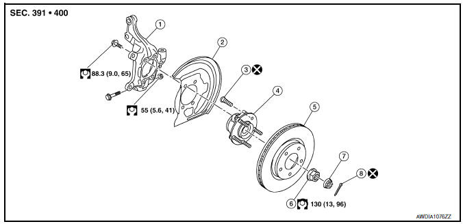
- Steering knuckle
- Splash guard
- Wheel stud
- Wheel hub and bearing
- Disc brake rotor
- Wheel hub lock nut
- Nut retainer
- Cotter pin
Removal and Installation
- Remove the wheel and tire using power tool. Refer to WT-47, "Exploded View".
- Remove the brake caliper torque member bolts, leaving the brake hose attached. Position the brake caliper aside with wire. Refer to BR-41, "BRAKE CALIPER ASSEMBLY : Removal and Installation".
CAUTION:
Do not depress the brake pedal while the brake caliper is removed.
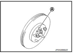
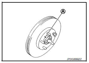
- Put alignment marks (A) on the disc brake rotor and on the wheel hub and bearing. Remove the disc brake rotor.
CAUTION:
Do not drop the disc brake rotor.
CAUTION:
Do not drop the disc brake rotor.
- Remove the wheel sensor bolt. Position the wheel sensor and the wheel sensor harness aside. Refer to BRC-106, "FRONT WHEEL SENSOR : Removal and Installation".
- Remove the cotter pin from the drive shaft.
- Remove the nut retainer from the wheel hub lock nut.
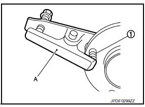
- Hold the wheel hub and bearing using Tool (A). Loosen the wheel hub lock nut.
Tool number (A): KV40104000 ( — )
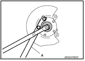
- Using a piece of wood and a suitable tool, tap on the wheel hub lock nut to disengage the drive shaft from the wheel hub and bearing.
CAUTION:
- Do not place the drive shaft joint at an extreme angle.
Also be careful not to overextend slide joint.
- Do not allow the drive shaft to hang down without support.
NOTE:
Use a suitable puller if the drive shaft cannot be separated from the wheel hub and bearing even after performing the above procedure.
- Remove the wheel hub lock nut.
- Remove the bolts and the wheel hub and bearing from the steering knuckle.
- Remove the splash guard from the steering knuckle.
- Suspend the drive shaft with suitable wire.
- If necessary, remove the wheel studs (1) from the wheel hub and bearing using a suitable tool (A).
CAUTION:
- Remove the wheel studs only when necessary.
- Do not hammer the wheel studs or damage to the wheel hub and bearing may occur.
- Pull out the wheel studs in a direction perpendicular to the wheel hub and bearing.
- Inspect the components. Refer to FAX-10, "Inspection".
INSTALLATION
Installation is in the reverse order of removal.
CAUTION:
- Do not reuse the wheel stud.
- Do not reuse the cotter pin.
- Place a washer (A) as shown to install the wheel studs (1) by using the tightening force of the nut (B).
CAUTION:
Check that there is no clearance between the wheel stud and the wheel hub and bearing.
- Clean the mating surfaces of the wheel hub lock nut and the wheel hub and bearing.
CAUTION:
- Do not apply lubricating oil to these mating surfaces.
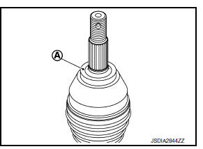
- Clean the mating surfaces of the joint sub-assembly and the wheel hub and bearing. Apply Molykote M77 lubricant to the surface (A) of the joint sub-assembly.
CAUTION:
Apply lubricant to cover the entire flat mating surface of the joint sub-assembly.
NOTE:
Always check with the Parts Department for the latest parts information.
Amount of lubricant : Refer to FAX-49, "Drive Shaft"
- Hold the wheel hub and bearing using Tool. Tighten the wheel hub lock nut.
CAUTION:
- Since the drive shaft is assembled by press-fitting, use a torque wrench to tighten the wheel hub lock nut. Do not use a power tool.
- Too much torque causes axle noise. Too little torque causes wheel bearing looseness. Tighten the wheel hub lock nut to the specification.
Tool number : KV40104000 ( — )
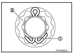
- When installing a the cotter pin (1) and the nut retainer (2), securely bend the cotter pin to prevent rattles.
- Align the matching marks (A) on the disc brake rotor and on the wheel hub and bearing.
- Complete the inspection. Refer to FAX-17, "Inspection".
Inspection
INSPECTION AFTER REMOVAL
Check the following items, and replace the part if necessary.
- Check components for deformation, cracks, and other damage.
- Check boots of transverse link and steering outer socket ball joint for breakage, axial end play, and swing torque.
- Transverse link: Refer to FSU-10, "Inspection".
- Steering outer socket: Refer to ST-8, "Inspection".
INSPECTION AFTER INSTALLATION
- Check the wheel sensor harness to be sure the connectors are fully seated.
- Check the wheel alignment. Refer to FSU-6, "Inspection".

 Front drive shaft boot
Exploded View
(LH)
Circular clip
Dust shield
Slide joint housing
Snap ring
Spider assembly
Boot band
Boot
Shaft
Damper band
Dynamic damper
Circular clip
Joint sub-assembly ...
Other materials:
Multiport Fuel Injection System or Engine Control System
Before connecting or disconnecting any harness connector for the
multiport fuel injection system or ECM:
Turn ignition switch to “OFF” position.
Disconnect negative battery terminal.
Otherwise, there may be damage to ECM.
Before disconnecting pressurized fuel line from ...
Dtc/circuit diagnosis
Eco mode switch
Component function check
1. Check eco mode switch operation
Turn ignition switch on.
Check ECO mode indicator lamp turns ON/OFF on combination meter when
turn ECO mode switch ON/
OFF.
Is the inspection result normal?
YES >> GO TO 2.
NO >> Proceed to DM ...
C1115 ABS Sensor [abnormal signal]
DTC Logic
DTC DETECTION LOGIC
DTC
Display Item
Malfunction detected condition
Possible causes
C1115
ABS SENSOR
[ABNORMAL SIGNAL]
When difference in wheel speed between any wheel
and others is detected while the vehicle is driven, because
of installation of t ...
