Nissan Sentra Service Manual: B1430, B1432 Seat belt pre-tensioner LH
Description
DTC B1430, B1432 SEAT BELT PRE-TENSIONER LH
The seat belt pre-tensioner LH is wired to the air bag diagnosis sensor unit. The air bag diagnosis sensor unit will monitor for opens and shorts in detected lines to the seat belt pre-tensioner LH.
PART LOCATION
Refer to SRC-5, "Component Parts Location".
DTC Logic
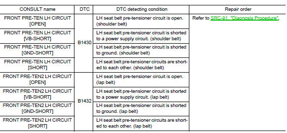
DTC DETECTION LOGIC
With CONSULT
DTC CONFIRMATION PROCEDURE (With CONSULT)
1.CHECK SELF-DIAG RESULT
- Turn ignition switch ON.
- Check for DTC using CONSULT.
Is the DTC detected? YES (Current DTC)>>Refer to SRC-91, "Diagnosis Procedure".
YES (Past DTC)>>GO TO 2.
NO >> Inspection End.
2.ERASE SELF-DIAG RESULT
Erase the DTC using CONSULT.
Can the DTC be erased? YES >> Inspection End.
NO >> Refer to SRC-91, "Diagnosis Procedure".
DTC CONFIRMATION PROCEDURE (Without CONSULT)
1.CHECK SELF-DIAG RESULT
- Turn ignition switch ON.
- Check the air bag warning lamp status. Refer to SRC-17, "Trouble Diagnosis without CONSULT".
NOTE:
SRS will not enter diagnosis mode if no malfunction is detected in user mode.
Is the DTC detected? YES >> Refer to SRC-91, "Diagnosis Procedure".
NO >> Inspection End.
Diagnosis Procedure
1.HARNESS CONNECTOR
Visually inspect all applicable harness connectors for the following:
- Visible damage to connector or terminal
- Loose terminal
- Poor connection
NOTE:
All harness connectors should be inspected from the air bag diagnosis sensor unit to the end component (including any in-line connectors).
Is the inspection result normal? YES >> GO TO 2.
NO >> Perform one of the following repairs:
- Visible damage: Replace the harness.
- Loose terminal: Secure the terminal.
- Poor connection: Secure the connection.
2.CONFIRM DTC
- Reconnect all harness connectors.
- Turn ignition switch ON.
- Check for DTC using CONSULT.
Is DTC still current? YES >> GO TO 3.
NO >> Refer to GI-39, "Intermittent Incident".
3.WIRING HARNESS
Check the wiring harness for visible damage.
NOTE:
The entire wiring harness should be inspected from the air bag diagnosis sensor unit to the end component (including any in-line connectors).
Is the inspection result normal? YES >> GO TO 4.
NO >> Replace the harness.
4.CONFIRM DTC
- Reconnect all harness connectors.
- Turn ignition switch ON.
- Check for DTC using CONSULT.
Is DTC still current? YES >> GO TO 5.
NO >> Refer to GI-39, "Intermittent Incident".
5.AIR BAG DIAGNOSIS SENSOR UNIT
- Replace the air bag diagnosis sensor unit. Refer to SR-28, "Removal and Installation".
- Turn ignition switch ON.
- Check for DTC using CONSULT
Is DTC still current? YES >> GO TO 6.
NO >> Clear DTC. Inspection End.
6.SEAT BELT PRE-TENSIONER LH
- Replace the seat belt pre-tensioner LH. Refer to SR-31, "Removal and Installation".
- Turn ignition switch ON.
- Check for DTC using CONSULT.
Is DTC still current? YES >> GO TO 7.
NO >> Clear DTC. Inspection End.
7.RELATED HARNESS
Replace the related harness.
>> END
 B1429 Seat belt buckle switch RH
Description
DTC B1429 SEAT BELT BUCKLE SWITCH RH
The air bag diagnosis sensor unit monitors the seat belt buckle switch RH
status. If the control unit detects an
open or short condition in the ci ...
 B1431, B1433 Seat belt pre-tensioner RH
Description
DTC B1431, B1433 SEAT BELT PRE-TENSIONER RH
The seat belt pre-tensioner RH is wired to the air bag diagnosis sensor unit.
The air bag diagnosis sensor unit
will monitor for opens and ...
Other materials:
Rear window defogger power supply and ground circuit
Description
Heats the heating wire with the power supply from the rear window defogger
relay to prevent the rear window
from fogging up.
Component function check
1. Check rear window defogger
Check that the heating wire of rear window defogger is heated when turning
the rear window defogge ...
Battery terminal with fusible link
Exploded view
Battery terminal with fusible link
Harness connector
Removal and installation
Removal
Loosen the battery terminal nuts and disconnect both battery negative and
positive terminals. Refer to
pg-50, "exploded view".
Caution:
To prevent damage to the parts, di ...
Precaution for Work
When removing or disassembling each component, be careful not to damage
or deform it. If a component
may be subject to interference, be sure to protect it with a shop cloth.
When removing (disengaging) components with a screwdriver or similar
tool, be sure to wrap the component
with a ...
