Nissan Sentra Service Manual: Rear window defogger power supply and ground circuit
Description
Heats the heating wire with the power supply from the rear window defogger relay to prevent the rear window from fogging up.
Component function check
1. Check rear window defogger
Check that the heating wire of rear window defogger is heated when turning the rear window defogger switch on.
Is the inspection result normal? Yes >> rear window defogger is ok.
No >> refer to def-33, "diagnosis procedure".
Diagnosis procedure
Regarding wiring diagram information, refer to def-20, "wiring diagram".
1. Check fuses
Check if any of the following fuses in IPDM E/R are blown.
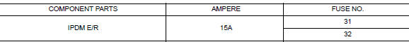
Is the inspection result normal? Yes >> go to 2.
No >> replace the blown fuse after repairing the affected circuit.
2. Check rear window defogger power supply circuit
- Turn ignition switch ON.
- Check voltage between ipdm e/r connector and ground.
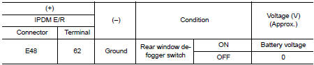
Is the inspection result normal? YES >> GO TO 3.
NO >> Perform rear window defogger relay diagnosis. Refer to DEF-32, "Diagnosis Procedure".
3. Check power supply circuit
- Turn ignition switch on.
- Check voltage between rear window defogger connector and ground.
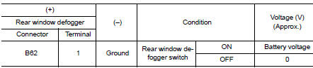
Is the inspection result normal? YES >> GO TO 4.
NO >> GO TO 5.
4. Check ground circuit
- Turn ignition switch off
- Disconnect rear window defogger.
- Check continuity between rear window defogger connector and ground.
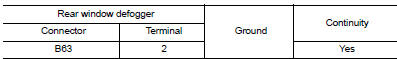
Is the inspection result normal? YES >> GO TO 6.
NO >> Repair or replace harness.
5. Check harness continuity
- Turn ignition switch OFF.
- Disconnect IPDM E/R.
- Check continuity between ipdm e/r connector and condenser connector.
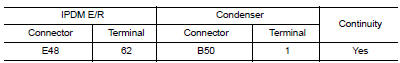
Is the inspection result normal? Yes >> replace condenser. Refer to def-49, "removal and installation".
No >> replace or repair harness.
6. Check filament
Check filament.
Refer to DEF-34, "Component Inspection".
Is the inspection result normal? YES >> Refer to GI-39, "Intermittent Incident".
NO >> Repair filament. Refer to DEF-47, "Inspection and Repair".
Component inspection
1. Check filament
Check the filament for damage or open circuits.
Refer to DEF-47, "Inspection and Repair".
Is the inspection result normal? YES >> Inspection End.
NO >> Repair filament. Refer to DEF-47, "Inspection and Repair".
 Rear window defogger relay
Description
Power is supplied to the rear window defogger with BCM control.
Component Function Check
1. Check rear window defogger relay power supply circuit
Turn ignition switch ON.
Check ...
 Driver side door mirror defogger
Description
Heats the heating wire with the power supply from the rear window defogger
relay to prevent the door mirror
from fogging up.
Component Function Check
Check that heating wire of doo ...
Other materials:
P1078 EVT Control position sensor
DTC Logic
DTC DETECTION LOGIC
DTC No.
CONSULT screen terms
(Trouble diagnosis content)
DTC detecting condition
Possible cause
P1078
EXH TIM SEN/CIRC-B1
(Exhaust valve timing control
position sensor circuit
bank 1)
An excessively high or low voltage from
...
B2205 vehicle speed
Description
The abs actuator and electric unit (control unit) provides a vehicle speed
signal to the combination meter via
can communication lines.
DTC Logic
Dtc detection logic
Dtc
Consult
Detection condition
Possible malfunction location
B2205
VEHICLE SPEED CIR ...
Trunk lid
Trunk lid assembly
Trunk lid assembly : exploded view
Trunk lid hinge LH/RH
Torsion bar LH/RH
Torsion bar clips
Trunk lid finisher (if equipped)
Emergency release handle
Emergency release handle clip
Emergency release handle cable
Trunk lid lock
Trunk lid bumpers
License lam ...
