Nissan Sentra Service Manual: Front drive shaft
6M/T
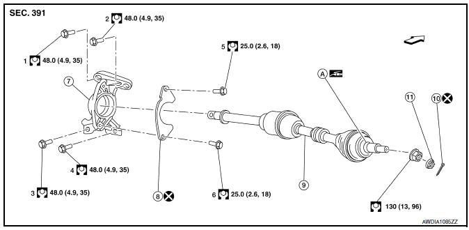
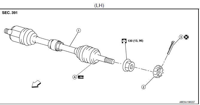
6M/T : Exploded View (LH)
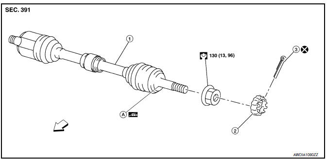
- Front drive shaft
- Nut retainer
- Cotter pin
- Molykote M77
 Front
Front
6M/T : Removal and Installation (LH)
NOTE:
When removing components such as hoses, tubes, lines, etc., cap or plug openings to prevent fluid from spilling.
REMOVAL
- Remove the wheel and tire using power tool. Refer to WT-47, "Exploded View".
- Drain the M/T fluid. Refer to TM-19, "Draining".
- Remove the brake caliper torque member bolts, leaving the brake hose attached. Position the brake caliper aside with wire. Refer to BR-41, "BRAKE CALIPER ASSEMBLY : Removal and Installation".
CAUTION:
Do not depress the brake pedal while the brake caliper is removed.
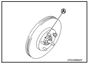
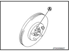
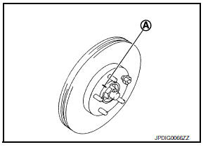
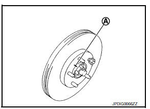
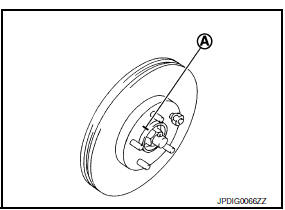
- Put alignment marks (A) on the disc brake rotor and on the wheel hub and bearing. Remove the disc brake rotor.
CAUTION:
Do not drop the disc brake rotor.
- Remove the wheel sensor bolt. Position the wheel sensor and the wheel sensor harness aside. Refer to BRC-106, "FRONT WHEEL SENSOR : Removal and Installation".
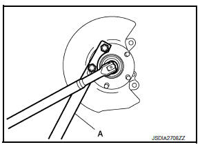
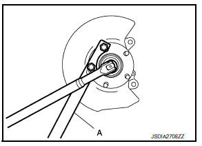
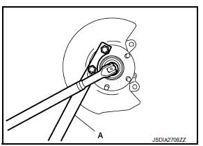
- Remove the cotter pin from the drive shaft.
- Remove the nut retainer from the wheel hub lock nut.
- Hold the wheel hub and bearing using Tool (A). Loosen the wheel hub lock nut.
Tool number (A): KV40104000 ( — )
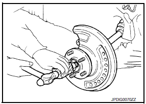
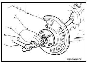
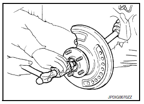
- Using a piece of wood and a suitable tool, tap on the wheel hub lock nut to disengage the drive shaft from the wheel hub and bearing.
CAUTION:
- Do not place the drive shaft joint at an extreme angle.
Also be careful not to overextend slide joint.
- Do not allow the drive shaft to hang down without support.
NOTE:
Use a suitable puller if the drive shaft cannot be separated from the wheel hub and bearing even after performing the above procedure.
- Remove the wheel hub lock nut.
- Remove the nut and bolt from the lower ball joint. Disconnect the steering knuckle from the transverse link.
- Remove the drive shaft from the wheel hub and bearing.
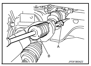
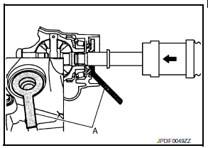
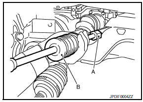
- Insert the Tool (A) between the shaft and the transaxle. Install a suitable tool (B) to the Tool (A). Remove the drive shaft from the transaxle.
CAUTION:
Confirm that the circular clip is attached to the drive shaft.
Tool number (A): KV40107500 ( – )
- Remove the differential side oil seal. Refer to TM-20, "Removal and Installation".
- Inspect the components. Refer to FAX-24, "6M/T : Inspection".
INSTALLATION
Installation is in the reverse order of removal.
TRANSAXLE SIDE
- Install a new differential side oil seal. Refer to TM-20, "Removal and Installation".
CAUTION:
Do not reuse the differential side oil seal.
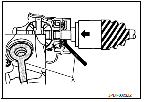
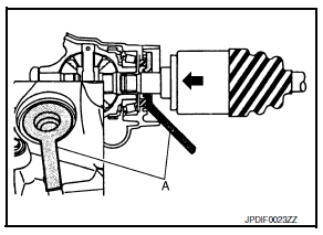
- Place Tool (A) onto the differential side oil seal to prevent damage to the oil seal while inserting the drive shaft. Slide drive shaft sliding joint and tap with a hammer to install securely.
CAUTION:
Check that circular clip is completely engaged.
Tool number (A): KV38107900 ( – )
- Refill the M/T oil. Refer to TM-19, "Refilling".
- Complete the inspection. Refer to FAX-17, "Inspection".
WHEEL HUB SIDE
- Clean the mating surfaces of the wheel hub lock nut and the wheel hub and bearing.
CAUTION:
Do not apply lubricating oil to these mating surfaces.
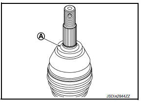
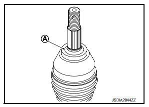
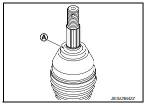
- Clean the mating surfaces of the joint sub-assembly and the wheel hub and bearing. Apply Molykote M77 lubricant to the surface (A) of the joint sub-assembly.
CAUTION:
Apply lubricant to cover the entire flat mating surface of the joint sub-assembly.
NOTE:
Always check with the Parts Department for the latest parts information.
Amount of lubricant : Refer to FAX-49, "Drive Shaft"
- Hold the wheel hub and bearing using Tool. Tighten the wheel hub lock nut.
CAUTION:
- Since the drive shaft is assembled by press-fitting, use a torque wrench to tighten the wheel hub lock nut. Do not use a power tool.
- Too much torque causes axle noise. Too little torque causes wheel bearing looseness. Tighten the wheel hub lock nut to the specification.
Tool number : KV40104000 ( — )
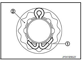
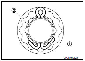
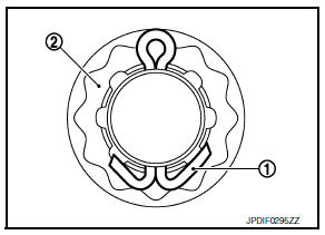
- When installing a the cotter pin (1) and the nut retainer (2), securely bend the cotter pin to prevent rattles.
CAUTION:
Do not reuse the cotter pin.
- Align the matching marks (A) on the disc brake rotor and on the wheel hub and bearing.
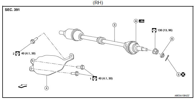
6M/T : Exploded View (RH)
1-6. Tightening order
- Support bearing bracket
- Support bearing bracket plate
- Front drive shaft
- Cotter pin
- Nut retainer
6M/T : Removal and Installation (RH)
REMOVAL
- Remove the wheel and tire using power tool. Refer to WT-47, "Exploded View".
- Drain the M/T fluid. Refer to TM-19, "Draining".
- Remove the brake caliper torque member bolts, leaving the brake hose attached. Position the brake caliper aside with wire. Refer to BR-41, "BRAKE CALIPER ASSEMBLY : Removal and Installation".
CAUTION:
Do not depress the brake pedal while the brake caliper is removed.
- Put alignment marks (A) on the disc brake rotor and on the wheel hub and bearing. Remove the disc brake rotor.
CAUTION:
Do not drop the disc brake rotor.
- Remove the wheel sensor bolt. Position the wheel sensor and the wheel sensor harness aside. Refer to BRC-106, "FRONT WHEEL SENSOR : Removal and Installation".
- Remove the cotter pin from the drive shaft.
- Remove the nut retainer from the wheel hub lock nut.
- Hold the wheel hub and bearing using Tool (A). Loosen the wheel hub lock nut.
Tool number (A): KV40104000 ( — )
- Using a piece of wood and a suitable tool, tap on the wheel hub lock nut to disengage the drive shaft from the wheel hub and bearing.
CAUTION:
- Do not place the drive shaft joint at an extreme angle.
Also be careful not to overextend slide joint.
- Do not allow the drive shaft to hang down without support.
NOTE:
Use a suitable puller if the drive shaft cannot be separated from the wheel hub and bearing even after performing the above procedure.
- Remove the wheel hub lock nut.
- Remove the bolts and the support bearing bracket plate.
- Remove the nut and bolt from the lower ball joint. Disconnect the steering knuckle from the transverse link.
- Remove the drive shaft from the wheel hub and bearing.
- Remove the drive shaft from the transaxle.
- Remove the differential side oil seal. Refer to TM-20, "Removal and Installation".
- If necessary, remove the support bearing bracket bolts and the support bearing bracket.
- Inspect the components. Refer to FAX-24, "6M/T : Inspection".
INSTALLATION
Installation is in the reverse order of removal.
TRANSAXLE SIDE
- Install a new differential side oil seal. Refer to TM-20, "Removal and Installation".
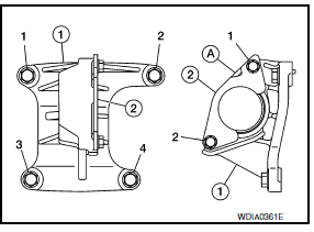
- When installing the support bearing bracket (1), note the following:
- Tighten the support bearing bracket bolts in 2 stages in the order of 1 to 4 as shown.
- Install the support bearing bracket plate (2) with the notch (A) upward. Tighten the support bearing bracket plate bolts in 2 stages in the order of 1 to 2 as shown.
CAUTION:
Do not reuse the support bearing bracket plate.
- Place Tool (A) onto the differential side oil seal to prevent damage to the oil seal while inserting the drive shaft. Slide drive shaft sliding joint and tap with a hammer to install securely.
Tool number (A): KV38107900 ( – )
- Refill the M/T oil. Refer to TM-19, "Refilling".
- Complete the inspection. Refer to FAX-17, "Inspection".
WHEEL HUB SIDE
- Clean the mating surfaces of the wheel hub lock nut and the wheel hub and bearing.
CAUTION:
Do not apply lubricating oil to these mating surfaces.
- Clean the mating surfaces of the joint sub-assembly and the wheel hub and bearing. Apply Molykote M77 lubricant to the surface (A) of the joint sub-assembly.
CAUTION:
Apply lubricant to cover the entire flat mating surface of the joint sub-assembly.
NOTE:
Always check with the Parts Department for the latest parts information.
Amount of lubricant : Refer to FAX-49, "Drive Shaft"
- Hold the wheel hub and bearing using Tool. Tighten the wheel hub lock nut.
CAUTION:
- Since the drive shaft is assembled by press-fitting, use a torque wrench to tighten the wheel hub lock nut. Do not use a power tool.
- Too much torque causes axle noise. Too little torque causes wheel bearing looseness. Tighten the wheel hub lock nut to the specification.
Tool number : KV40104000 ( — )
- When installing a the cotter pin (1) and the nut retainer (2), securely bend the cotter pin to prevent rattles.
CAUTION:
Do not reuse the cotter pin.
- Align the matching marks (A) on the disc brake rotor and on the wheel hub and bearing.
- Complete the inspection. Refer to FAX-17, "Inspection".
6M/T : Inspection
INSPECTION AFTER REMOVAL
Check the following items and replace the part if necessary.
- Move the joint up/down, left/right, and in the axial directions. Check for motion that is not smooth and for significant looseness.
- Check the boot for cracks, damage, and grease leaks.
- Check the support bearing bracket for cracks, deformation, and other damage.
INSPECTION AFTER DISASSEMBLY
Check the following items and replace the part if necessary.
Shaft
Check the shaft for runout, cracks, or other damage. Replace the shaft if necessary.
Dynamic Damper
Check the dynamic damper for cracks or wear.
Joint Sub-Assembly
Check the following:
- Joint sub-assembly for rough rotation and excessive axial looseness.
- The inside of the joint sub-assembly for entry of foreign material.
- Joint sub-assembly for compression scars, cracks, and fractures inside of the joint sub-assembly.
Replace the joint sub-assembly if there are any non-standard conditions of components.
Housing and spider assembly
Replace the housing and spider assembly if there is scratching or wear of the housing roller contact surface or the spider roller contact surface.
NOTE:
Replace the housing and spider assembly as a set.
Support Bearing (RH)
Verify the support bearing rolls freely and is free from noise, cracks, pitting or wear. Replace the support bearing if there are any non-standard conditions.
Support Bearing Bracket (RH)
Check the support bearing bracket for cracks or damage. Replace the support bearing bracket if there are any non-standard conditions.
INSPECTION AFTER INSTALLATION
- Check the wheel sensor harness to be sure the connectors are fully seated.
- Check the wheel alignment. Refer to FSU-6, "Inspection".
EXCEPT 6M/T
EXCEPT 6M/T : Exploded View
- Front drive shaft
- Nut retainer
- Cotter pin
- Molykote M77
 Front
Front
1-2 Tightening order
- Front drive shaft
- Heat shield
- Cotter pin
- Nut retainer
 Front
Front
EXCEPT 6M/T : Removal and Installation
NOTE:
When removing components such as hoses, tubes, lines, etc., cap or plug openings to prevent fluid from spilling.
REMOVAL
- Remove the wheel and tire using power tool. Refer to WT-47, "Exploded View".
- Remove the brake caliper torque member bolts, leaving the brake hose attached. Position the brake caliper aside with wire. Refer to BR-41, "BRAKE CALIPER ASSEMBLY : Removal and Installation".
CAUTION:
Do not depress the brake pedal while the brake caliper is removed.
- Put alignment marks (A) on the disc brake rotor and on the wheel hub and bearing. Remove the disc brake rotor.
CAUTION:
Do not drop the disc brake rotor.

- Remove the wheel sensor bolt. Position the wheel sensor and the wheel sensor harness aside. Refer to BRC-106, "FRONT WHEEL SENSOR : Removal and Installation".
- Remove the cotter pin from the drive shaft.
- Remove the nut retainer from the wheel hub lock nut.
- Hold the wheel hub and bearing using Tool (A). Loosen the wheel hub lock nut.
Tool number (A): KV40104000 ( — )
- Using a piece of wood and a suitable tool, tap on the wheel hub lock nut to disengage the drive shaft from the wheel hub and bearing.
CAUTION:
- Do not place the drive shaft joint at an extreme angle.
Also be careful not to overextend slide joint.
- Do not allow the drive shaft to hang down without support.
NOTE:
Use a suitable puller if the drive shaft cannot be separated from the wheel hub and bearing even after performing the above procedure.
- Remove the wheel hub lock nut.
- Remove the nut and bolt from the lower ball joint. Disconnect the steering knuckle from the transverse link.
- Remove the drive shaft from the wheel hub and bearing.
- For the (RH) drive shaft, remove the bolts and the heat shield.
- Insert the Tool (A) between the shaft and the transaxle. Install a suitable tool (B) to the Tool (A). Remove the drive shaft from the transaxle.
CAUTION:
Confirm that the circular clip is attached to the drive shaft.
Tool number (A): KV40107500 ( – )
- Remove the differential side oil seal. Refer to TM-271, "Removal and Installation".
- Inspect the components. Refer to FAX-24, "6M/T : Inspection".
INSTALLATION
Transaxle Side
Installation is in the reverse order of removal.
- Install a new differential side oil seal. Refer to TM-271, "Removal and Installation".
CAUTION:
Do not reuse the differential side oil seal.
- Place Tool (A) onto the differential side oil seal to prevent damage to the oil seal while inserting the drive shaft. Slide drive shaft sliding joint and tap with a hammer to install securely.
CAUTION:
Check that circular clip is completely engaged.
Tool number (A): KV38107900 ( – )
- Check the CVT fluid level. Check the CVT for leaks. Refer to TM-250, "Inspection".
- Complete the inspection. Refer to FAX-17, "Inspection".
Wheel Hub Side
- Clean the mating surfaces of the wheel hub lock nut and the wheel hub and bearing.
CAUTION:
Do not apply lubricating oil to these mating surfaces.
- Clean the mating surfaces of the joint sub-assembly and the wheel hub and bearing. Apply Molykote M77 lubricant to the surface (A) of the joint sub-assembly.
CAUTION:
Apply lubricant to cover the entire flat mating surface of the joint sub-assembly.
NOTE:
Always check with the Parts Department for the latest parts information.
Amount of lubricant : Refer to FAX-49, "Drive Shaft"
- Hold the wheel hub and bearing using Tool. Tighten the wheel hub lock nut.
CAUTION:
- Since the drive shaft is assembled by press-fitting, use a torque wrench to tighten the wheel hub lock nut. Do not use a power tool.
- Too much torque causes axle noise. Too little torque causes wheel bearing looseness. Tighten the wheel hub lock nut to the specification.
Tool number : KV40104000 ( — )
- When installing a the cotter pin (1) and the nut retainer (2), securely bend the cotter pin to prevent rattles.
CAUTION:
Do not reuse the cotter pin.
- Align the matching marks (A) on the disc brake rotor and on the wheel hub and bearing.
- Complete the inspection. Refer to FAX-17, "Inspection".
EXCEPT 6M/T : Inspection
INSPECTION AFTER REMOVAL
Check the following items and replace the part if necessary.
- Move the joint up/down, left/right, and in the axial directions. Check for motion that is not smooth and for significant looseness.
- Check the boot for cracks, damage, and grease leaks.
INSPECTION AFTER DISASSEMBLY
Check the following items and replace the part if necessary.
Shaft
Check the shaft for runout, cracks, or other damage. Replace the shaft if necessary
Dynamic Damper
Check the dynamic damper for cracks or wear.
Joint Sub-Assembly
Check the following:
- Joint sub-assembly for rough rotation and excessive axial looseness.
- The inside of the joint sub-assembly for entry of foreign material
- Joint sub-assembly for compression scars, cracks, and fractures inside of the joint sub-assembly.
Replace the joint sub-assembly if there are any non-standard conditions of components.
Housing and spider assembly
Replace the housing and spider assembly if there is scratching or wear of the housing roller contact surface or the spider roller contact surface.
NOTE:
Replace the housing and spider assembly as a set.
INSPECTION AFTER INSTALLATION
- Check the wheel sensor harness to be sure the connectors are fully seated.
- Check the wheel alignment. Refer to FSU-6, "Inspection".
 Transaxle side
TRANSAXLE SIDE : Removal and Installation
Remove boot after drive shaft is removed from the vehicle.
For drive shaft removal and installation, follow the instructions bellow.
6M/T: Refer to FAX ...
 Unit disassembly and assembly
Front drive shaft ...
Other materials:
Rear seat
Exploded View
Rear seatback assembly (RH)
Seatback striker
Seatback latch release knob
Seatback latch assembly
Seatback silencer (RH)
Rear seatback frame (RH)
Seatback latch release knob finisher
Rear seat bolster trim (RH)
Rear seat bolster pad (RH)
Rear seat bolster (RH)
...
Steering knuckle
Exploded View
Steering knuckle
Splash guard
Wheel stud
Wheel hub and bearing
Disc brake rotor
Wheel hub lock nut
Nut retainer
Cotter pin
Removal and Installation
REMOVAL
Remove the wheel and tire using power tool. Refer to WT-47, "Exploded
View".
Remove ...
C1716, C1717, C1718, C1719 Transmitter (pressure data)
DTC Logic
NOTE:
The Signal Tech II Tool (J-50190) can be used to perform the following
functions. Refer to the Signal Tech II
User Guide for additional information.
Activate and display TPMS transmitter IDs
Display tire pressure reported by the TPMS transmitter
Read TPMS DTCs
Register ...
