Nissan Sentra Service Manual: Sport mode control
SPORT MODE CONTROL : System Description
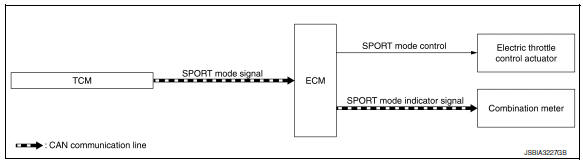
SYSTEM DIAGRAM
SYSTEM DESCRIPTION
- SPORT mode that keeps high engine revolution and provides direct feel and acceleration performance suitable for driving on winding road.
- ECM receives an SPORT mode signal from TCM via CAN communication and improves drivability by controlling the throttle movement.
- ECM transmits an SPORT mode indicator lamp signal to the combination meter via CAN communication.
NOTE:
For the details of the SPORT mode, refer to DMS-63, "SPORT MODE CONTROL : System Description" (CVT models) or DMS-43, "SPORT MODE CONTROL : System Description" (M/T models).
 Eco mode control
ECO MODE CONTROL : System Description
SYSTEM DIAGRAM
SYSTEM DESCRIPTION
ECM receives an ECO mode signal from combination meter via CAN
communication and improves the fuel
economy by con ...
 Operation
...
Other materials:
Secondary speed sensor
Exploded View
Transaxle assembly
O-ring
Secondary speed sensor
Vehicle front
Always replace after every
disassembly.
: NВ·m (kg-m, in-lb)
: Genuine NISSAN CVT Fluid NS-3
Removal and Installation
REMOVAL
Disconnect the secondary speed sensor connector.
Remove the s ...
Can communication
CAN COMMUNICATION : System Description
CAN (Controller Area Network) is a serial communication line for real time
application. It is an on-vehicle multiplex
communication line with high data communication speed and excellent error
detection ability. Many electronic
control units are equipped ...
Periodic maintenance
CVT FLUID
Inspection
FLUID LEAKAGE
Check transaxle surrounding area (oil seal and plug etc.) for fluid
leakage.
If anything is found, repair or replace damaged parts and adjust
CVT fluid level. Refer to TM-251, "Adjustment".
Replacement
CVT fluid : Refer to TM-288, & ...
