Nissan Sentra B18 (2020-2025) Service Manual: Dtc/circuit Diagnosis
Power Supply and Ground Circuit
Av Control Unit
Diagnosis Procedure
Diagnosis Procedure
-
CHECK FUSE
-
Check that the following fuse is not blown:
Terminal No.
Signal name
Fuse No.
Capacity
19
Battery power supply
40
20 A
Is the fuse blown?
YES >>Replace the blown fuse after repairing the affected circuit.
NO >>GO TO 2.
-
-
CHECK POWER SUPPLY CIRCUIT
-
-
Ignition switch OFF.
-
Disconnect AV control unit connector.
-
Check voltage between AV control unit connector and ground.
AV control unit
—
Voltage
(Approx.)
Connector
Terminal
M103
19
Ground
Battery voltage
-
Is the inspection result normal?
YES >>GO TO 3.
NO >>Repair or replace harness or connectors.
-
-
CHECK GROUND CIRCUIT
-
Check continuity between AV control unit connector and ground.
AV control unit
—
Continuity
Connector
Terminal
M103
20
Ground
Yes
Is the inspection result normal?
YES>>Inspection End.
NO>>Repair or replace harness or connectors.
-
Rear View Camera Image Signal Circuit
Diagnosis Procedure
Diagnosis Procedure
-
CHECK CAMERA POWER SUPPLY CIRCUIT CONTINUITY
-
-
Ignition switch OFF.
-
Disconnect AV control unit connector and rear view camera connector.
-
Check continuity between AV control unit connector and rear view camera connector.
AV control unit
Rear view camera
Continuity
Connector
Terminal
Connector
Terminal
M104
33
B30
1
Yes
-
Check continuity between AV control unit connector and ground.
AV control unit
—
Continuity
Connector
Terminal
M104
33
Ground
No
-
Is inspection result normal?
YES >>GO TO 2.
NO >>Repair or replace harness or connectors.
-
-
CHECK CAMERA POWER SUPPLY VOLTAGE
-
-
Connect AV control unit connector and rear view camera connector.
-
Ignition switch ON.
-
Shift the selector lever to R (reverse).
-
Check voltage between AV control unit connector and ground.
AV control unit
(−)
Condition
Voltage
(Approx.)
(+)
Connector
Terminal
M104
33
Ground
Selector lever is in “R�.
6.0 V
-
Is inspection result normal?
YES >>GO TO 3.
NO >>Replace AV control unit. Refer to Removal and Installation.
-
-
CHECK CAMERA IMAGE SIGNAL CIRCUIT CONTINUITY
-
-
Ignition switch OFF.
-
Disconnect AV control unit connector and rear view camera connector.
-
Check continuity between AV control unit connector and rear view camera connector.
AV control unit
Rear view camera
Continuity
Connector
Terminal
Connector
Terminal
M104
52
B30
3
Yes
-
Check continuity between AV control unit connector and ground.
AV control unit
—
Continuity
Connector
Terminal
M104
52
Ground
No
-
Is inspection result normal?
YES >>GO TO 4.
NO >>Repair or replace harness or connectors.
-
-
CHECK CAMERA GROUND CIRCUIT CONTINUITY
-
Check continuity between AV control unit connector and rear view camera connector.
AV control unit
Rear view camera
Continuity
Connector
Terminal
Connector
Terminal
M104
32
B30
2
Yes
Is inspection result normal?
YES >>GO TO 5.
NO >>Repair or replace harness or connectors.
-
-
CHECK CAMERA IMAGE SIGNAL
-
-
Connect AV control unit connector and rear view camera connector.
-
Ignition switch ON.
-
Shift the selector lever to R (reverse).
-
Check signal between AV control unit connector and ground.
AV control unit
(−)
Condition
Reference value
(+)
Connector
Terminal
M104
52
Ground
Camera image displayed.
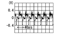
-
Is inspection result normal?
YES >>Replace AV control unit. Refer to Removal and Installation.
NO >>Replace rear view camera. Refer to Removal and Installation.
-
Other materials:
Automatic Emergency Braking (AEB) with Pedestrian Detection
WARNING
Failure to carefully follow all warnings and instructions for proper use of
the Automatic Emergency Braking (AEB) with Pedestrian Detection system could result
in serious injury or death.
The AEB with Pedestrian Detection system on the Nissan Sentra is a supplemental
driver assis ...
U2118-87 Can Comm Err (intelligent Key)
Dtc Description
DTC Description
DESCRIPTION
CAN (Controller Area Network) is a serial communication
line for real time applications. It is an on-Nissan Sentra vehicle multiplex communication
line with high data communication speed and excellent error detection
ability. Modern Nissan ...
Preparation. Preparation
Preparation
Special Service Tool
Special Service Tool
The actual shape of the tools may differ from those
illustrated here.
Tool number
(TechMate No.)
Tool name
...