Nissan Sentra B18 (2020-2025) Service Manual: B2a1a Rear Camera
Dtc Description
DTC Description
DTC DETECTION LOGIC
|
DTC No. |
CONSULT screen terms (Trouble diagnosis content) |
DTC detection condition |
|
|---|---|---|---|
|
B2A1A-38 |
Rear camera (Rear camera image signal) |
Diagnosis condition |
Ignition switch ON |
|
Signal (terminal) |
RV video signal circuit (terminal 20) |
||
|
Threshold |
RV video signal circuit is open or short |
||
|
Diagnosis delay time |
ŌĆö |
||
POSSIBLE CAUSE
-
RV video signal circuit
-
Rear camera
-
Around view monitor control unit
FAIL-SAFE
-
Camera image may not be displayed.
-
MOD (Moving Object Detection) function is stopped.
Confirmation Procedure
Confirmation Procedure
-
PERFORM DTC CONFIRMATION PROCEDURE
-
 CONSULT
-
Ignition switch ON.
-
Ignition switch OFF and wait at least 30 seconds.
-
Ignition switch ON and wait at least 30 seconds or more.
-
Select ŌĆ£Self Diagnostic ResultŌĆØ mode of ŌĆ£AVMŌĆØ.
-
Check DTC.
-
Is DTC B2A1AŌĆō38 detected?
YES >>Proceed to DTC Diagnosis Procedure.
NO >>To check malfunction symptom before repair: Refer to Intermittent Incident.
NO >>Confirmation after repair: Inspection End.
-
Dtc Diagnosis Procedure
DTC Diagnosis Procedure
-
CHECK CONTINUITY OF REAR CAMERA POWER SUPPLY AND GROUND CIRCUIT
-
-
Ignition switch OFF.
-
Disconnect around view monitor control unit connector and rear camera connector.
-
Check continuity between around view monitor control unit connector and rear camera connector.
Around view monitor control unit
Rear camera
Continuity
Connector
Terminal
Connector
Terminal
B72
17
B69
7
Yes
18
8
-
Check continuity between around view monitor control unit connector and ground.
Around view monitor control unit
ŌĆö
Continuity
Connector
Terminal
B72
18
Ground
No
-
Is the inspection result normal?
YES >>GO TO 2.
NO >>Repair harness or connector.
-
-
CHECK VOLTAGE OF REAR CAMERA POWER SUPPLY
-
-
Connect around view monitor control unit connector and rear camera connector.
-
Ignition switch ON.
-
Check voltage between around view monitor control unit connector and ground.
(+)
(ŌłÆ)
Condition
Voltage
(Approx.)
Around view monitor control unit
Connector
Terminal
B72
18
Ground
ŌĆ£CAMERAŌĆØ switch is ON or shift position is ŌĆ£RŌĆØ.
6.0 V
-
Is inspection result normal?
YES >>GO TO 3.
NO >>Replace around view monitor control unit. Refer to Removal and Installation.
-
-
CHECK CONTINUITY OF REAR CAMERA IMAGE SIGNAL CIRCUIT
-
-
Ignition switch OFF.
-
Disconnect around view monitor control unit connector and rear camera connector.
-
Check continuity between around view monitor control unit connector and rear camera connector.
Around view monitor control unit
Rear camera
Continuity
Connector
Terminal
Connector
Terminal
B72
19
B69
1
Yes
20
5
-
Check continuity between around view monitor control unit harness connector and ground.
Around view monitor control unit
ŌĆö
Continuity
Connector
Terminal
B72
20
Ground
No
-
Is inspection result normal?
YES >>GO TO 4.
NO >>Repair harness or connector.
-
-
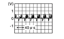
CHECK REAR CAMERA IMAGE SIGNAL
-
-
Connect around view monitor control unit connector and rear camera connector.
-
Ignition switch ON.
-
Check signal between around view monitor control unit connector.
Around view monitor control unit
Condition
Reference value
Connector
Terminals
(+)
(ŌĆö)
B72
20
19
ŌĆ£CAMERAŌĆØ switch is ON or shift position is ŌĆ£RŌĆØ.
-
Is inspection result normal?
YES >>Replace around view monitor control unit. Refer to Removal and Installation.
NO >>Replace rear camera. Refer to Removal and Installation.
-
Other materials:
Ecu Diagnosis Information. Abs Actuator and Electric Unit (control Unit)
Abs Actuator and Electric Unit (control Unit)
Values on the Diagnosis Tool
Values on the
Diagnosis Tool
Note:
The following table includes information (items)
inapplicable to this Nissan Sentra vehicle: For information (items) applicable to
this vehicle, refer to CONSULT display ...
Power Supply, Ground & Circuit Elements. Basic Inspection
Battery
How to Handle Battery
How to Handle Battery
CAUTION:
If it becomes necessary to start the engine with
a booster battery and jumper cables, use a 12-volt booster
battery.
After connecting battery cables, ensure that they
...
U0073-00 Can Comm Circuit
Dtc Description
DTC Description
DTC DETECTION LOGIC
DTC No.
CONSULT screen terms
(Trouble diagnosis content)
DTC detection condition
...