Nissan Sentra Service Manual: Dtc/circuit diagnosis
U1000 can comm circuit
Description
Refer to lan-7, "can communication system : system description".
DTC Logic
Dtc detection logic
Note:
U1000 can be set if a module harness was disconnected and reconnected, perhaps during a repair. Confirm that there are actual can diagnostic symptoms and a present dtc by performing the self diagnostic result procedure.
| Consult display | Dtc detection condition | Possible cause |
| Can comm circuit [u1000] | When any listed module cannot communicate with CAN communication signal continuously for 2 seconds or more with ignition switch ON | In CAN communication system, any item (or
items) of the following listed below is malfunctioning.
|
Diagnosis Procedure
1. Perform self diagnostic result
- Turn ignition switch on and wait for 2 second or more.
- Check “SELF- DIAG RESULTS”.
Is “can comm circuit” displayed? Yes >> perform can diagnosis as described in diagnosis section of consult operation manual.
No >> refer to gi-39, "intermittent incident".
U1010 control unit (can)
Dtc logic
Dtc detection logic
| Consult display | Dtc detection condition | Possible cause |
| Control unit (can) [u1010] | Bcm detected internal can communication circuit malfunction. | Bcm |
Diagnosis procedure
1.Replace bcm
When dtc “u1010” is detected, replace bcm.
>> Replace bcm. Refer to bcs-73, "removal and installation".
B2614 acc relay circuit
Dtc logic
Dtc detection logic
| Consult display | Dtc detecting condition | Possible cause |
| Acc relay circuit [b2614] | An immediate operation of accessory relay is requested by bcm, but there is no response for more than 1 second. |
|
Dtc confirmation procedure
1.Perform dtc confirmation procedure
- Turn ignition switch to ACC, and wait for 1 second or more.
- Check “self-diagnosis result” of bcm with consult.
Is DTC detected? YES >> Go to PCS-82, "Diagnosis Procedure".
NO >> Inspection End.
Diagnosis procedure
Regarding wiring diagram information, refer to pcs-70, "wiring diagram".
1.Check accessory relay-2 control signal
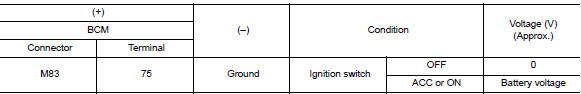
Check voltage between bcm connector m83 and ground.
Is the inspection result normal? YES >> Replace BCM. Refer to BCS-73, "Removal and Installation".
NO >> GO TO 2.
2.Check accessory relay-2 control signal circuit
- Turn ignition switch off.
- Disconnect BCM connector M83 and accessory relay-2.
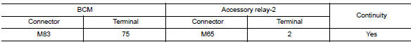
- Check continuity between bcm connector m83 and accessory relay-2 connector m65.
- Check continuity between bcm connector m83 and ground.

Is the inspection result normal? Yes >> go to 3.
No >> repair or replace harness.
3.Check accessory relay-2
Refer to pcs-83, "component inspection".
Is the inspection result normal? Yes >> replace bcm. Refer to bcs-73, "removal and installation".
No >> replace accessory relay-2.
Component inspection
1.Check accessory relay-2
- Turn ignition switch off.
- Remove accessory relay-2.
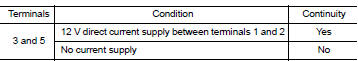
- Check the continuity between accessory relay-2 terminals.
Is the inspection result normal? Yes >> inspection end.
No >> replace accessory relay-2.
B2615 blower relay circuit
Dtc logic
Dtc detection logic
| Consult display | Dtc detection condition | Possible cause |
| BLOWER RELAY CIRCUIT [B2615] | An immediate operation of front blower motor relay is requested by bcm, but there is no response for more than 1 second. |
|
Dtc confirmation procedure
1.Perform dtc confirmation procedure
- Turn ignition switch on, and wait for 1 second or more.
- Check “self-diagnosis result” with consult.
Is dtc detected? Yes >> go to pcs-84, "diagnosis procedure".
No >> inspection end.
Diagnosis procedure
Regarding wiring diagram information, refer to pcs-70, "wiring diagram".
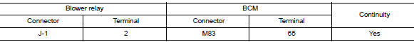
1. Check blower relay power supply circuit
- Turn ignition switch OFF.
- Disconnect blower relay.
- Disconnect bcm connector m83.
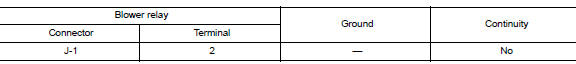
- Check continuity between blower relay connector J-1 and BCM connector M83.
- Check continuity between blower relay connector j-1 and ground.
Is the inspection result normal? YES >> GO TO 2.
NO >> Repair or replace harness or connectors.
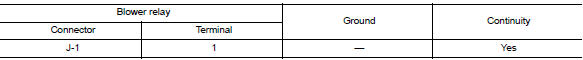
2. Check blower relay ground circuit
- Check continuity between blower relay connector j-1 and ground.
Is the inspection result normal? Yes >> go to 3.
No >> repair or replace harness or connectors.
3. Check blower motor relay
Perform the relay component inspection. Refer to pcs-85, "component inspection".
Is the inspection result normal? Yes >> go to 4.
No >> replace blower motor relay.
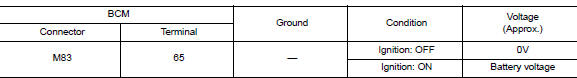
4. Check blower relay power supply (bcm)
Check voltage between bcm connector m83 and ground.
Is the inspection result normal? Yes >> refer to gi-39, "intermittent incident".
No >> replace bcm. Refer to bcs-73, "removal and installation".
Component inspection
1.Check blower relay
- Turn blower switch OFF.
- Remove blower relay.
- Check the continuity between blower relay terminals.
Is the inspection result normal? Yes >> inspection end.
No >> replace blower relay
B2616 ignition relay circuit
Dtc logic
Dtc detection logic
| Consult display | Dtc detection condition | Possible cause |
| Ignition relay circuit [b2616] | An immediate operation of ignition relay-2 is requested by BCM, but there is no response for more than 1 second. |
|
Dtc confirmation procedure
1. Perform self diagnostic result
- Turn ignition switch on under the following conditions, and wait for at least 1 second.
- Cvt selector lever is in the p (park) or n (neutral) position.
- Release brake pedal
- Perform self diagnostic result.
Is dtc b2616 detected? Yes >> refer to pcs-86, "diagnosis procedure".
No >> inspection end.
Diagnosis procedure
Regarding wiring diagram information, refer to pcs-70, "wiring diagram".
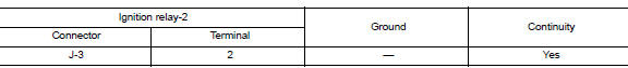
1. Check ignition relay-2 power supply circuit
- Turn ignition switch off.
- Disconnect bcm connector m83.
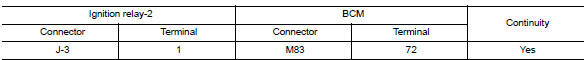
- Check continuity between ignition relay-2 connector j-3 and bcm connector m83.
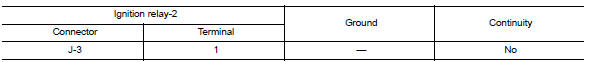
- Check continuity between ignition relay-2 connector j-3 and ground.
Is the inspection result normal? YES >> GO TO 2.
NO >> Repair or replace harness or connectors.
2. Check ignition relay-2 ground circuit
- Check continuity between ignition relay-2 connector j-3 and ground.
Is the inspection result normal? YES >> GO TO 3.
No >> repair or replace harness or connectors.
3. Check ignition relay-2
Perform the relay component inspection. Refer to pcs-87, "component inspection".
Is the inspection result normal? Yes >> go to 4.
No >> replace ignition relay-2.
4. Check ignition relay-2 power supply (bcm)
Check voltage between bcm connector m83 and ground.
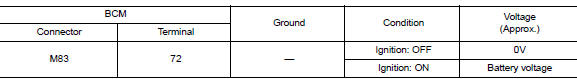
Is the inspection result normal? Yes >> refer to gi-39, "intermittent incident".
No >> replace bcm. Refer to bcs-73, "removal and installation".
Component inspection
1.Check ignition relay-2
- Turn ignition switch OFF.
- Remove ignition relay-2.
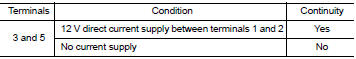
- Check the continuity between ignition relay-2 terminals.
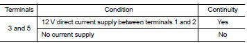
Is the inspection result normal? Yes >> inspection end.
No >> replace ignition relay-2.
B2618 bcm
Dtc logic
Dtc detection logic
Note:
- If dtc b2618 is displayed with dtc u1000, first perform the trouble diagnosis for dtc u1000. Refer to pcs-80, "dtc logic".
- If dtc b2618 is displayed with dtc u1010, first perform the trouble diagnosis for dtc u1010. Refer to pcs-81, "dtc logic".
| Consult display | Dtc detection condition | Possible cause |
| BCM [B2618] | An immediate operation of ignition relay-1 is requested by bcm, but there is no response for more than 1 second |
|
Dtc confirmation procedure
1. Perform self diagnostic result
- Turn ignition switch on under the following conditions, and wait for at least 1 second.
- Cvt selector lever is in the p (park) or n (neutral) position.
- Release brake pedal
- Perform self diagnostic result.
Is dtc b2618 detected? Yes >> refer to pcs-88, "diagnosis procedure".
No >> inspection end.
Diagnosis procedure
Regarding wiring diagram information, refer to pcs-70, "wiring diagram".
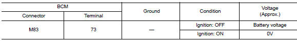
1.Check ignition relay-1 control signal
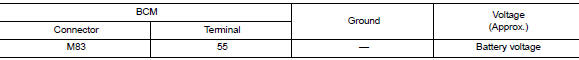
Check voltage between bcm connector m83 and ground.
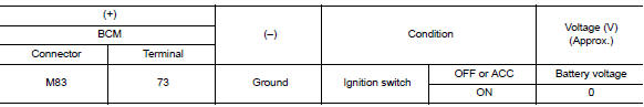
Is the inspection result normal? Yes >> replace bcm. Refer to bcs-73, "removal and installation".
No >> go to 2.
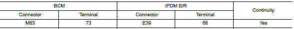
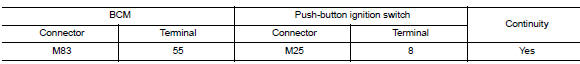
2.Check ignition relay-1 control signal circuit
- Turn ignition switch off
- Disconnect bcm connector m83 and ipdm e/r connector e39.
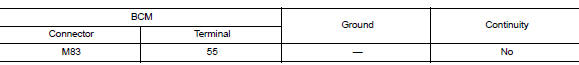
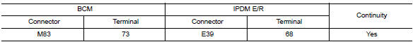
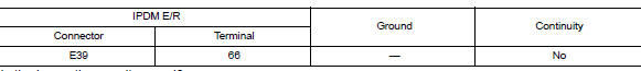
- Check continuity between bcm connector m83 and ipdm e/r connector e39.
- Check continuity between bcm connector m83 and ground.
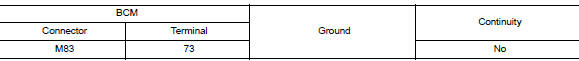
Is the inspection result normal? Yes >> go to 3.
No >> repair or replace harness.
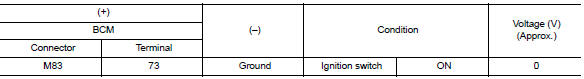
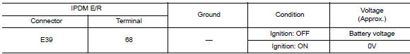
3.Check voltage of ignition relay-1 control signal circuit (ipdm e/r side)
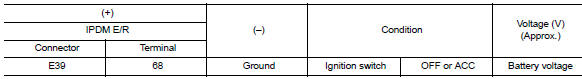
- Connect ipdm e/r connector.
- Check voltage between ipdm e/r connector e39 and ground.
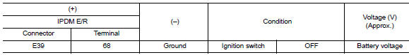
Is the inspection result normal? Yes >> replace bcm. Refer to bcs-73, "removal and installation".
No >> replace ipdm e/r.
B261A push-button ignition switch
DTC Logic
Dtc detection logic
| Consult display | Dtc detection condition | Possible cause |
| Push-button ignition switch [b261a] | Bcm detects a difference of signal for 1 second or
more between the following information:
|
|
Dtc confirmation procedure
1. Perform self diagnostic result
- Press the push-button ignition switch under the following conditions, and wait for at least 1 second.
- Cvt selector lever is in the p (park) or n (neutral) position.
- Release the brake pedal.
- Perform self diagnostic result.
Is dtc b261a detected? Yes >> refer to pcs-90, "diagnosis procedure".
No >> inspection end.
Diagnosis Procedure
Regarding wiring diagram information, refer to pcs-70, "wiring diagram".
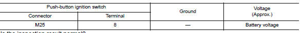
1. Check push-button ignition switch output signal (push-button ignition switch)
- Disconnect push-button ignition switch connector.
- Check voltage between push-button ignition switch connector m25 and ground.
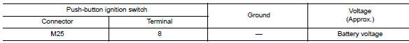
Is the inspection result normal? Yes >> go to 2.
No >> go to 4.
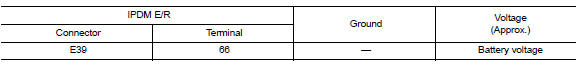
2. Check ignition switch output signal (ipdm e/r)
Check voltage between ipdm e/r connector e39 and ground.
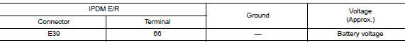
Is the inspection result normal? Yes >> go to 3.
No >> replace ipdm e/r. Refer to pcs-30, "removal and installation".
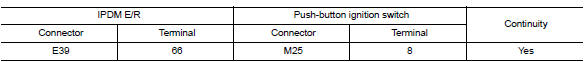
3. Check push-button ignition switch circuit (ipdm e/r)
- Turn ignition switch off.
- Disconnect IPDM E/R connector E39 and BCM connector M83.
- Check continuity between ipdm e/r connector e39 and push-button ignition switch connector m25.
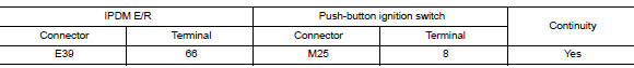
- Check continuity between ipdm e/r connector e39 and ground.
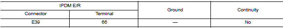
Is the inspection result normal? Yes >> refer to gi-39, "intermittent incident".
No >> repair or replace harness or connectors.
4. Check ignition switch output signal (bcm)
Check voltage between BCM connector M83 and ground.
Is the inspection result normal? YES >> GO TO 5.
NO >> Replace BCM. Refer to BCS-73, "Removal and Installation".
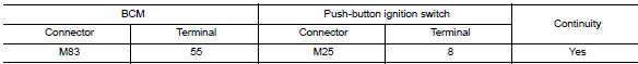
5. Check push-button ignition switch circuit (bcm)
- Turn ignition switch OFF.
- Disconnect bcm connector m83 and ipdm e/r connector e39.
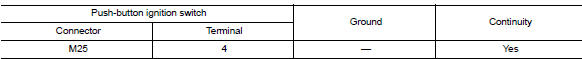
- Check continuity between bcm connector m83 and push-button ignition switch connector m25.
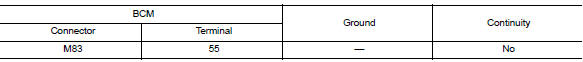
- Check continuity between BCM connector M83 and ground.
Is the inspection result normal? Yes >> refer to gi-39, "intermittent incident".
No >> repair or replace harness or connectors.
B26f1 ignition relay
Dtc logic
Dtc detection logic
| Consult display | Dtc detecting condition | Possible cause |
| IGN RELAY OFF [B26F1] | BCM transmits the ignition relay control signal, but does not receive ignition switch ON signal (CAN) from IPDM E/R. |
|
Dtc confirmation procedure
1.Perform dtc confirmation procedure
- Turn ignition switch ON, and wait for 2 seconds or more.
- Check “self-diagnosis result” with consult.
Is dtc detected? Yes >> go to pcs-92, "diagnosis procedure".
No >> inspection end.
Diagnosis procedure
Regarding wiring diagram information, refer to pcs-70, "wiring diagram".
1.Check ipdm e/r self-diagnostic result
- Turn ignition switch on.
- Erase the dtc of ipdm e/r.
- Turn ignition switch off.
- Turn ignition switch on and check the dtc again.
Is dtc detected? Yes >> repair or replace the malfunctioning part. Refer to pcs-20, "dtc index".
No >> go to 2.
2.Check ignition relay-1 control signal (ipdm e/r)
Check voltage between bcm connector m83 and ground.
Is the inspection result normal? Yes >> go to 3.
No >> replace bcm. Refer to bcs-73, "removal and installation".
3.Check ignition relay-1 control signal circuit (ipdm e/r)
- Turn ignition switch off.
- Disconnect bcm connector m83 and ipdm e/r connector m39.
- Check continuity between bcm connector m83 and ipdm e/r connector e39.
Is the inspection result normal?
Yes >> replace ipdm e/r. Refer to pcs-30, "removal and installation".
No >> repair or replace harness.
B26f2 ignition relay
Dtc logic
Dtc detection logic
| Consult display | Dtc detecting condition | Possible cause |
| Ign relay on [b26f2] | BCM transmits the ignition relay control signal, but does not receive ignition switch ON signal (CAN) from IPDM E/R. |
|
Dtc confirmation procedure
1.Perform dtc confirmation procedure
- Turn ignition switch ON, and wait for 2 seconds or more.
- Check “self-diagnosis result” with consult.
Is DTC detected? YES >> Go to PCS-94, "Diagnosis Procedure".
NO >> Inspection End.
Diagnosis procedure
Regarding Wiring Diagram information, refer to PCS-70, "Wiring Diagram".
1.Check ipdm e/r self-diagnostic result
- Turn ignition switch on.
- Erase the dtc of ipdm e/r.
- Turn ignition switch off.
- Turn ignition switch on and check the dtc again.
Is DTC detected? YES >> Repair or replace the malfunctioning part. Refer to PCS-20, "DTC Index".
NO >> GO TO 2.
2.Check ignition relay-1 control signal (ipdm e/r)
- Turn ignition switch off.
- Check voltage between IPDM E/R connector E39 and ground.
Is the inspection result normal? Yes >> replace ipdm e/r.
No >> go to 3.
3.Check ignition relay-1 control signal circuit - 1 (ipdm e/r)
- Turn ignition switch off.
- Disconnect bcm connector m83 and ipdm e/r connector e39.
- Check continuity between ipdm e/r connector e39 and ground.
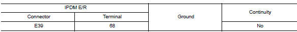
Is the inspection result normal?
Yes >> go to 4.
No >> repair or replace harness.
4.Check ignition relay-1 control signal circuit - 2 (ipdm e/r)
- Connect ipdm e/r connector e39.
- Check voltage between ipdm e/r connector e39 and ground.
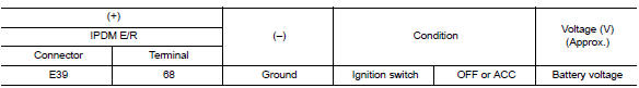
Is the inspection result normal? Yes >> replace bcm. Refer to bcs-73, "removal and installation".
No >> replace ipdm e/r. Refer to pcs-30, "removal and installation".
B26f6 bcm
DTC Logic
Dtc detection logic
Note:
- If dtc b26f6 is displayed with dtc u1000, first perform the trouble diagnosis for dtc u1000. Refer to pcs-80, "dtc logic".
- If dtc b26f6 is displayed with dtc u1010, first perform the trouble diagnosis for dtc u1010. Refer to pcs-81, "dtc logic".
| Consult display | Dtc detection condition | Possible cause |
| Bcm [b26f6] | Ignition relay ON signal is not transmitted from IPDM E/R (CAN) when BCM turns ignition relay ON. | Bcm |
Dtc confirmation procedure
1.Perform dtc confirmation procedure
- Turn ignition switch on, and wait for 0.5 Seconds or more.
- Check “Self-diagnosis result” of BCM with CONSULT.
Is dtc detected? Yes >> go to pcs-96, "diagnosis procedure".
No >> inspection end.
Diagnosis Procedure
Regarding wiring diagram information, refer to pcs-70, "wiring diagram".
1. Check self diagnostic result for ipdm e/r
Perform self diagnostic result for IPDM E/R.
Are any DTCs detected? YES >> Refer to PCS-20, "DTC Index".
NO >> GO TO 2
2. Check ignition relay-1 power supply (ipdm e/r)
Check voltage between ipdm e/r connector e39 and ground.
Is the inspection result normal? YES >> Replace IPDM E/R. Refer to PCS-30, "Removal and Installation".
NO >> GO TO 3.
3. Check ignition relay-1 power supply (bcm)
Check voltage between bcm connector m83 and ground.
Is the inspection result normal? Yes >> refer to gi-39, "intermittent incident".
No >> replace bcm. Refer to bcs-73, "removal and installation".
Push-button ignition switch
Component function check
1.Check function
- Select “PUSH SW” in “Data Monitor” of BCM with CONSULT.
- Check the push-button ignition switch signal under the following conditions.
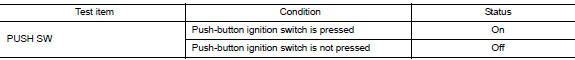
Is the indication normal? Yes >> inspection end.
No >> go to pcs-98, "diagnosis procedure".
Diagnosis procedure
Regarding Wiring Diagram information, refer to PCS-70, "Wiring Diagram".
1. Check push-button ignition switch output signal (push-button ignition switch)
- Turn ignition switch OFF.
- Disconnect push-button ignition switch connector and ipdm e/r connector e39.
- Check voltage between push-button ignition switch connector M25 and ground.
Is the inspection result normal? Yes >> go to 3.
No >> go to 2.
2. Check push-button ignition switch circuit (bcm)
- Disconnect bcm connector m83.
- Check continuity between bcm connector m83 and push-button ignition switch connector m25.
- Check continuity between bcm connector m83 and ground.
Is the inspection result normal? Yes >> replace bcm. Refer to bcs-73, "removal and installation".
No >> repair or replace harness or connectors.
3. Check ignition switch output signal (ipdm e/r)
Check voltage between ipdm e/r connector e39 and ground.
Is the inspection result normal? Yes >> go to 5.
No >> go to 4.
4. Check push-button ignition switch circuit (ipdm e/r)
- Disconnect bcm connector m83.
- Check continuity between ipdm e/r connector e39 and push-button ignition switch connector m25.
- Check continuity between IPDM E/R connector E39 and ground.
Is the inspection result normal? Yes >> replace ipdm e/r. Refer to pcs-30, "removal and installation".
No >> repair or replace harness or connectors.
5.Check push-button ignition switch ground circuit
Check continuity between push-button ignition switch connector M25 and ground.
Is the inspection result normal? YES >> GO TO 6.
NO >> Repair or replace harness or connectors.
6.Check push-button ignition switch
Refer to pcs-99, "component inspection".
Is the inspection result normal? Yes >> refer to gi-39, "intermittent incident".
No >> replace push-button ignition switch. Refer to pcs-102, "removal and installation".
Component inspection
1.Check push-button ignition switch
- Turn ignition switch OFF.
- Disconnect push-button ignition switch connector.
- Check continuity between push-button ignition switch terminals.
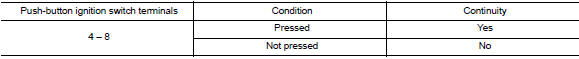
Is the inspection result normal? YES >> Inspection End.
No >> replace push-button ignition switch.
 Basic inspection
Diagnosis and repair work flow
Work flow
Overall sequence
Detailed flow
1.Get information for symptom
Get detailed information from the customer about the symptom (the
condition and the ...
 Symptom diagnosis
Push-button ignition switch does not operate
Description
Check that vehicle is under the condition shown in “Conditions of vehicle”
before starting diagnosis, and check
each symptom.
N ...
Other materials:
Auto operation does not operate but manual operate normally (driver side)
Diagnosis Procedure
1.PERFORM INITIALIZATION PROCEDURE
Initialization procedure is executed and operation is confirmed.
Refer to PWC-29, "Work Procedure".
Is the inspection result normal?
YES >> INSPECTION END
NO >> GO TO 2.
2.CHECK ENCODER CIRCUIT
Check encoder cir ...
Vehicle security system (if so equipped)
The vehicle security system provides visual and
audible alarm signals if someone opens the doors
when the system is armed. It is not, however, a
motion detection type system that activates when
a vehicle is moved or when a vibration occurs.
The system helps detect vehicle theft but cannot
prev ...
ID registration procedure
Description
This procedure must be performed after replacing wheels, transmitters or the
BCM, or rotating wheels.
Work Procedure
TPMS ID registration can be performed using one of the following procedures:
Transmitter Activation tool (J-45295-A) with CONSULT (preferred method)
Signal Tec ...
